 |
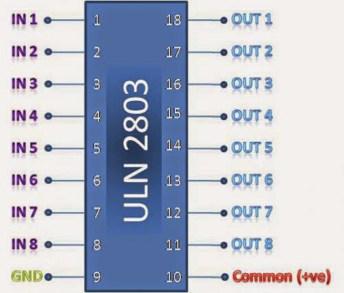
| IC ULN2803 Pin Diagram |
ULN2803 is a High voltage, high current Transistor Array IC used especially with Microcontrollers where we need to drive high power loads. Thic IC consists of a eight NPN Darlington connected transistors with common Clamp diodes for switching the loads connected to the output. This IC is widely used to drive high loads such Lamps, relays, motors etc. It is usually rated at 50v/500mA. This article brings out the working of ULN2803 IC and how to use it in a circuit.
PURPOSE OF ULN2803:
Most of the Chips operates with low level signals such as TTL, CMOS, PMOS, NMOS which operates at the range of (0-5)v and are incapable to drive high power inductive loads. However this chip takes low level input signals (TTL) and use that to switch/turn off the higher voltage loads that is connected to the output side.
| Work from anywhere on any device and access your Windows Applications with a virtual cloud desktop by CloudDesktopOnline.com |
| For cloud related business software such as SharePoint, Office365, try Apps4Rent |
WORKING OF ULN2803 IC:
The ULN2803 IC consists of eight NPN Darlington pair which provides the proper current amplification required by the loads. We all know that the transistors are used to amplify the current but here Darlington transistor pairs are used inside the IC to make the required amplification.
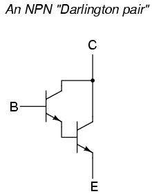 |
| Darlington Pair |
A Darlignton pair is two transistors that act as a single transistor providing high current gain. In this pair the current amplified by the first transistor is further amplified by the next transistor providing high current to the output terminal.
When no base voltage is applied that when is no signal is given to the input pins of the IC , there will be no base current and transistor remains in off state. When high logic is fed to the input both the transistors begin to conduct providing a path to ground for the external load that the output is connected. Thus when an input is applied corresponding output pin drops down to zero there by enabling the load connected to complete its path.

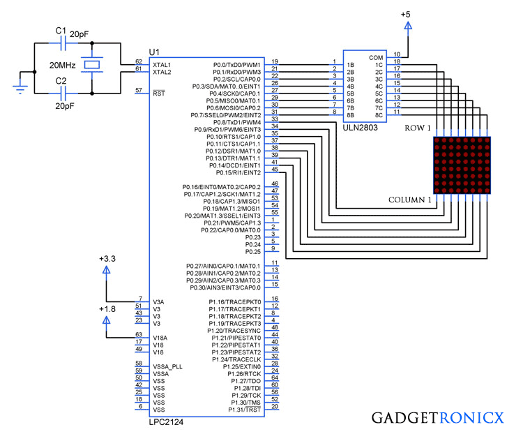

I have a 555/4017 board that I’m trying to drive a ULN2803 to power an LED array. Is the 4017 so “weak” that it cannot signal the ULN? I get no response from my circuit, past the indicator LEDS on my chaser board.
http://bigbelectronics.in/product.php?product=uln2803apg-octal-high-voltage-high-current-darlington-transistor-arrays
Highly unlikely according to ULN2803 datasheet 1mA input current is enough to activate the output. Another thing I would like to point out is that ULN2803 sinks current from its output pin and not source it. You may need to connect your LED array accordingly
The 7017 should be sufficient to drive an LED directly. you say an array so maybe there is a lot of current you need. At any rate, to answer you directly, no, the 4017 is far from being ‘too weak’ to drive the 2803. The 2803 are Darlington pair transistors — which means you can practically spit on an input to make it work. you cannot be ‘too weak’ with any other TTL/CMOS chip to drive them.
Could these be used in any audio application? I was wondering if this could be used as a gate like the TDA4070 used in old synthesizers and organs to sum the notes into one output.