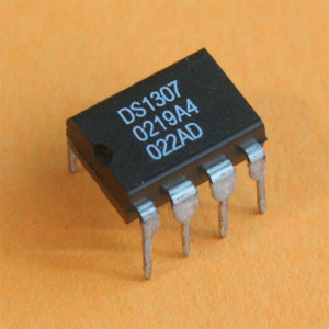
Real time clock chip RTC DS1307 is a widely used chip that provides accurate time and date information for external applications. These chips provide seconds,minutes,hours, day,month and year, it literally serves as a digital calendar. This chip only consumes less power and space , hence widely used in many embedded applications.
FEATURES OF RTC DS1307:
- This chip is capable of operating in either 24 hour or 12 hour format and can be changed by the user.
- The end of the month is automatically adjusted with fewer 31 months including the leap year corrections.
- It is capable of sensing power cut off from external supply and automatically switches to alternative battery supply connected to it.
- Less power consumption and small size makes it to use in all level of applications.
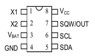
PIN DIAGRAM OF DS1307:
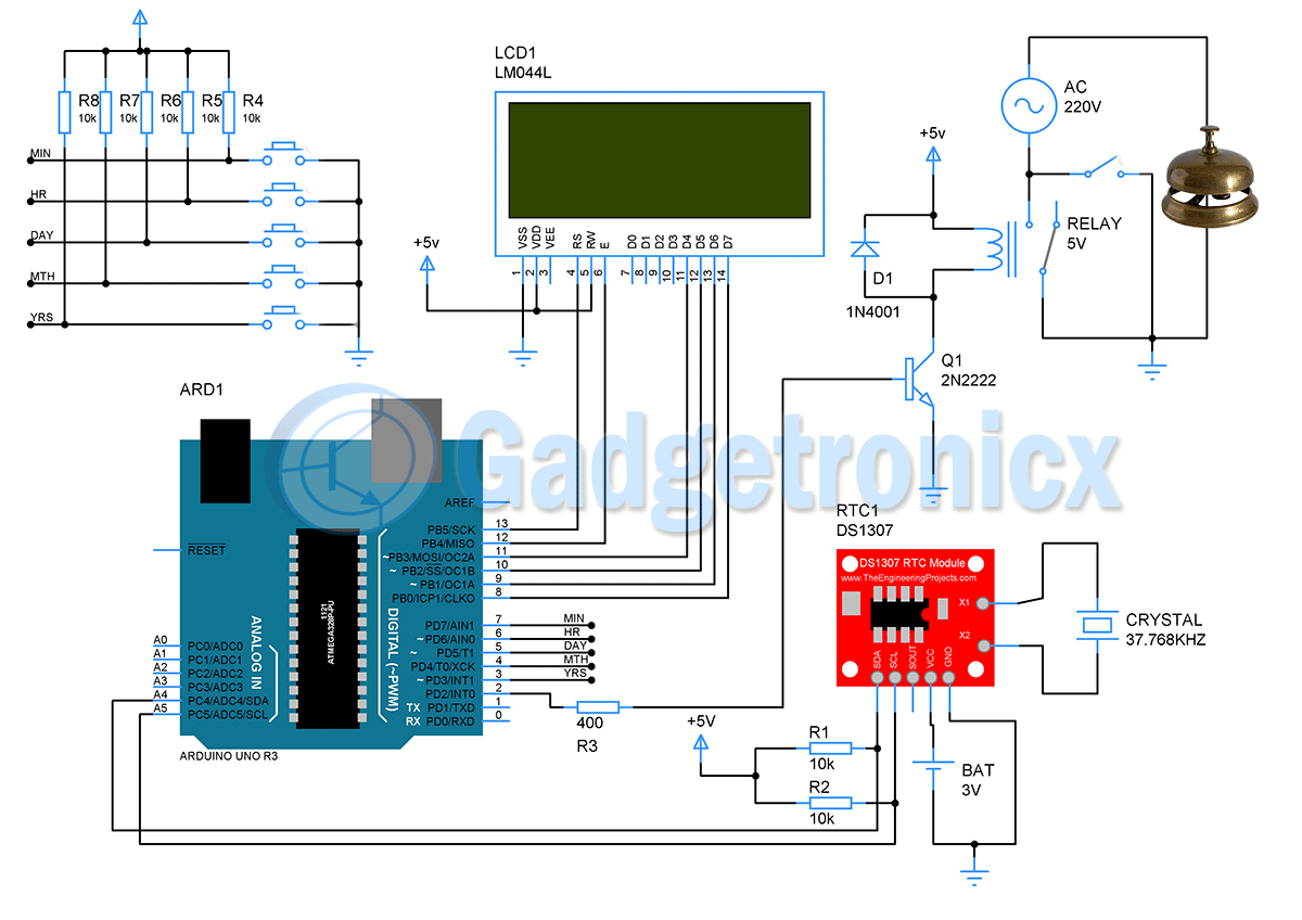
X1 and X2:These are the pins used to connect an external crystal oscillator to provide the clock source for the chip. According to the datasheet quartz crystal of 32.768 kHz should be used along with this chip.
VBAT :This pin is used to connect a +3V lithium battery to provide supply when the external supply voltage is not available. This pin should be grounded when not in use.
SQW/OUT: This output pin provides pulse ranging from frequency 1 kHz, 4kHz, 8 kHz or 32 kHz and needs a pull up resistor to operate.
SCL and SDA : These two pins used for carrying data in the I2C bus and must be connected to the SCL and SDA pins of the Microcontroller.
VCC and GND: These pins are supply and ground pins for the chip.
ADDRESS MAPPING FOR DS1307:
The DS1307 has a total of 64 bytes of RAM with address ranging from 00H to 3FH where the first seven bytes are used for time values while the next byte is the control register which controls the SQW/OUT pin in the chip. The rest of the bytes from 08H to 3FH is available for general purpose data storage.
CONTROL REGISTER:
REGISTER POINTER:
This DS1307 chip holds a register pointer that marks the byte that will be accessed next for the operation. After each read/write operation the register pointer is automatically incremented which is highly useful in multibyte read write.
TIME FORMAT IN RTC DS1307:
The data such as time, minute, year etc are given stored in the BCD format. As you can see in the address mapping that each byte was allotted to values such as seconds, minute, hour,day, month and year. Since the representation of data was in BCD format the lower four bits count up to where as top four/three bits count the rest of the data values.
For example consider value of “seconds” is 52 which was represented as
| MSB (Top four digits) | LSB (Bottom 4 digits) |
| 0101 – 5 | 0010 – 2 |
By writing or reading this data byte from or to the address 00H will give the seconds value. In the hours register 02H bit 5 will set the hours as 12 hour AM/PM format or 23 hours format. If you are not familiar with the BCD system use this Decimal to BCD converter tool.
The same kind of data representation goes for minutes, hours, month and year where the value ranges from
- Seconds – 0 to 60
- Minute – 0 to 60
- Hours – 0 to 12 or 0 to 23 based on the format we use.
- Month – 0 to 12
- Year – 0 to 99
WRITING TO OR READING FROM DS1307:
In order to perform the read or write operation in the DS1307 you need to follow the below steps.
- To access DS1307 we need to transmit the address of the chip + direction bit which specifies the read or write operation right after the START condition is initiated by the controller.
- Transmit the address DS1307 1101000 (will be specified in the datasheet) + “0” bit for write operation or “1” for read operation.
- You can set the register pointer address by transmitting the respective data byte address from 00H to 06H and then the read/write operation can be performed.
- Remember that the value of the register pointer will be automatically incremented which will help for multiple read or write operations.
Coding and interfacing tutorial of this DS1307 chip will be added soon in this site.




how this chip will provide real time of different zone of the world
Uttam Dutta,
It will give you “real time” meaning the chip itself will keep track of the time and all you have to do is read the value. It don’t know any time zones just keep track of the time from the value you set.