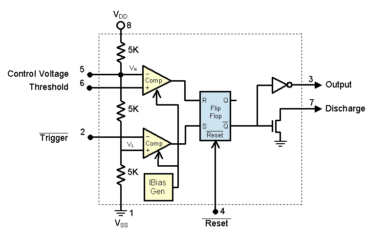
The working of IC 555 is very important to be aware of since it is widely used in many applications. It is widely used for producing delays, square waves, activators and so on. The working of IC 555 is governed by internal components you see in the below diagram.
WORKING OF IC 555:
In this IC there are two comparators which is meant to compare incoming voltages. These comparators drive a RS flip flop and this in turn activates a discharge transistor. A capacitor will be connected to this pin. Output from Flip flop will will be inverted to the output pin of 555 IC.
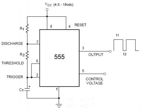
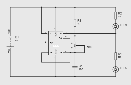
Kindly refer to the below circuit. This is most commonly used Multivibrator built using IC 555. We will use the below circuit and above internal diagram to explain 555 working. This working takes place in two cycles: Charging and Discharging cycle. This charging and discharging occurs to Capacitor C2 connected to discharge pin 2 in the circuit shown below.
CHARGING CYCLE:
Lets assume capacitor connected to pin 2 is in discharged state when the above circuit is turned ON. The input voltage to trigger pin connected to bottom comparator will be low. Non inverting terminal of this comparator will be at +1/3 Vcc. At this point flip flop inputs will be in the a state S=1, R = 0. Looking at the truth table below, we will know the output of Flip flop Q’ will be low. This will turn the discharge transistor OFF. A complementary of this signal i.e a high state will be at the output pin 3 of IC 555.
Now the capacitor C2 begins to charge via resistor R1 and R2. After a point of time capacitor voltage will be more than +1/3 Vcc and this feeds the trigger pin of IC 555. Now input of flip flop will be at S=0, R = 0 which leave the output Q’ in the previous state ( refer the truth table ). Output of IC 555 will remain at high state. The capacitor will continue to charge until it reaches +2/3Vcc.
DISCHARGING CYCLE:
The top comparator inputs are fed Threshold and Control pins. The control voltage was internally wired to +2/3 Vcc using three 5K resistors. User can manually use this control voltage pin by feeding desired input voltage to it or connect it to GND via a capacitor if we intend to use internal +2/3 Vcc. In the above circuit it is left floating which is not preferred ( explained later ).
When capacitor voltage exceeds +2/3 Vcc , it is fed to threshold pin of IC 555. At this point the input to Flip flop changes to S=0 and R =1 . This will force Q’ output to high state. 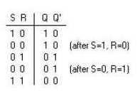


A high output from the flip flop saturates the discharge transistor and turn it ON. Now the capacitor C2 which was charging so far will be start discharging through this transistor. This discharging current passes through R2 before going into discharge pin. The complementary signal out of the flip flop goes into the pin 3 as output. At this stage the output obtained at the pin 3 of the IC will be low.
The capacitor discharges up to level of +1/3Vcc, when the cap voltage drops below +1/3 Vcc. The trigger voltage will be low comparing to +1/3 Vcc therefore flip flop input pins will have the state S=1, R =0 and output of Q’ goes low. This turns off the discharge transistor and stops cap from discharging.
The capacitor will enter the charging cycle again. This charging and discharging continues producing a output of highs and lows which forms a square wave of fixed frequency.
SUMMARY:
From the above we can understand basic two things. To get low output from timer 555 voltage in the threshold pin must exceed +2/3 Vcc and it also turns the discharge transistor ON.
To force the output to high state the voltage in the trigger pin must drop below +1/3 Vcc. This also turns the discharge transistor OFF.
A voltage may be applied to the control input to change threshold level. When not in use it is advised to connect a capacitor of 0.01nF between pin 5 and ground to prevent false triggering from noise.
RESET PIN:
The pin 4 can be used to reset 555. Connecting this pin to logic low will keep the IC 555 active. When Reset is pulled low 555 will go into inactive state.
555 WORKING VIDEO EXPLANATION:
Hope you find this article informative, checkout 555 IC circuits in our website. If you have any queries, comments or feedback do leave them in the comments section below.

So cool! I do thank you so much both for this anf for the other posts. Really nice.