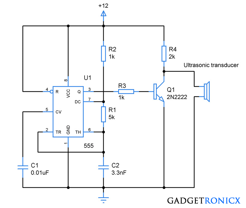
Ultrasonic sound waves are high frequency waves which is inaudible to human ear. It also had hell lot of applications in this world like range detection,machinery flaw detection etc. This Ultrasonic receiver circuit demonstrates the building of ultrasonic wave receiver which matches with the transmitter which was published previously in our site.
Read about : Ultrasonic transmitter circuit
WORKING OF ULTRASONIC RECEIVER CIRCUIT:
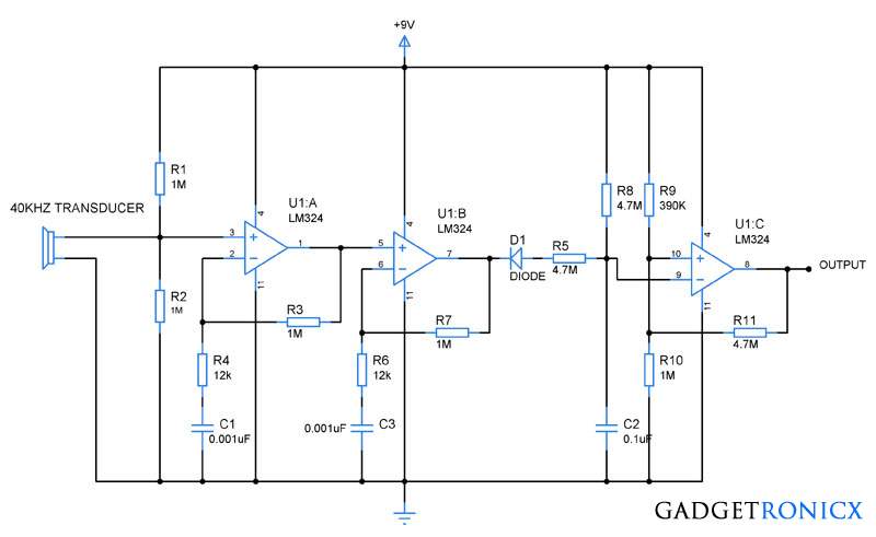
This circuit uses a simple ultrasonic receiver ( transducer) which converts the incoming ultrasonic wave to equivalent voltage. The signal was then passed through a non inverting amplifier built using Quad Op amp IC LM324. The gain of the amplifier can be controlled using a feedback resistor R3 connected from output to the inverting terminal.
Then this signal is further passed to the next stage of non inverting amplifier. There the signal was further amplified and the output was obtained from the pin 7 of the LM324 IC . The signal is then rectified using a diode and passed through a Resistor R5 and Capacitor C2 to prevent the false triggering in the output.
Final stage of the op amp was wired as an comparator which gives high output when ever a ultrasonic wave is detected by the transducer and low signal whenever there is no wave detected by the transducer.
This circuit along with the transmitter can be used to build simple robots in which it will assist the robot to evade the obstacles lying ahead them. Also can be used in range detection when used with a Microcontroller.
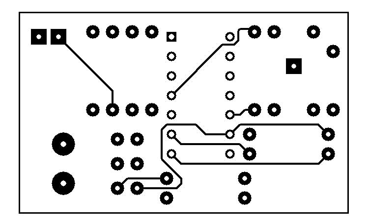
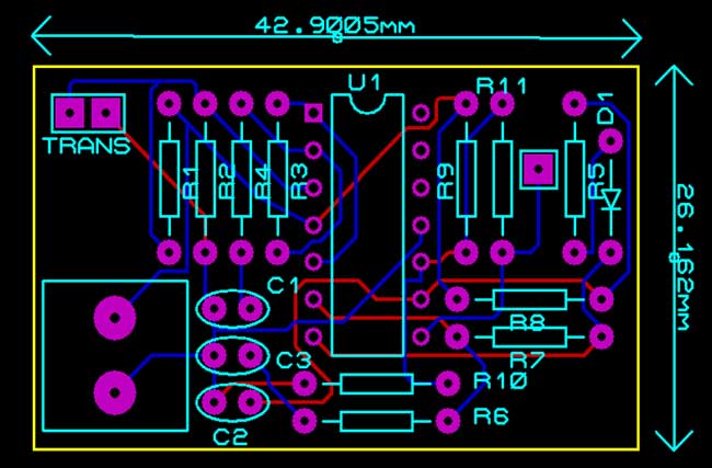
PCB DESIGN:
|
|
 |
| TOP VIEW |


Does it recognise any noises or vibrations as a 40 KHz signal?
How the output on the second stage will pass through the reversed diode D1 it will actually block the signal, isn’t it??
I need ability to pick up ultrasonic sound between 25KHz and 45KHz.
Would this circuit be able to do that?
Ultrasonic receiver circuit using Opamp LM324
Your top and bottom view of the PCB are both the same.
Can you correct the bottom on this post>
Hey Bro… I need a ultrasonic transceiver circuit.. that transmits and receives in one line…help me if you can.
what is the value of the diode (D1)?
Omar,
1N4001 will suffice.
Anyone successfully built this and captured a 40KHz signal?
Thanks
Has anyone actually tested this circuit; using proteus simulation and with given values, it doesn’t look like it triggers on 40KHz – frequency response triggers around 5KHz.
Hello frank
any progress regarding the pcb design?… sorry for bothering u with this
Abir,
Please have some patience, lot of things in my plate currently. Am working on it, will post the result by the end of this week. Cheers
thanx a lot frank
Abir,
Added the PCB design in the article along with the dimensions of the board. Also i have sent the gerber files to your mail with further instructions, take a look.
looks lyk ur top and bottom view uploaded here are same, plz check
can anyone here provide me a pcb board design of this circuit diagram? so that i can order some ?
Abir,
Will publish the design asap.
Thnx frank