Ultrasonic sound waves are high frequency waves which is inaudible to human ear. It also had hell lot of applications in this world like range detection,machinery flaw detection etc. This Ultrasonic receiver circuit demonstrates the building of ultrasonic wave receiver which matches with the transmitter which was published previously in our site.
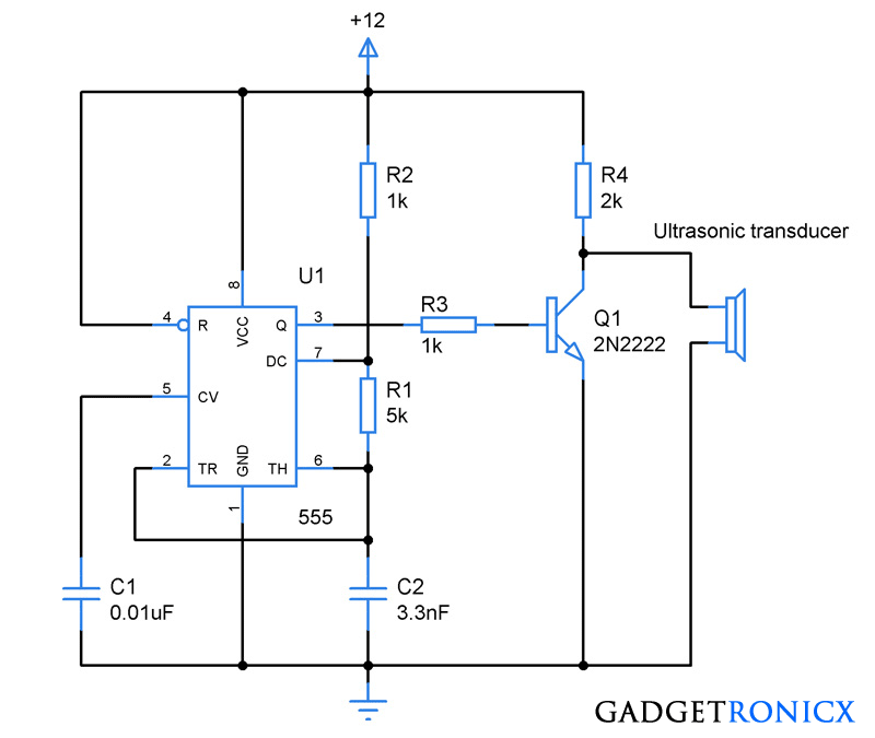
Read about : Ultrasonic transmitter circuit
WORKING OF ULTRASONIC RECEIVER CIRCUIT:
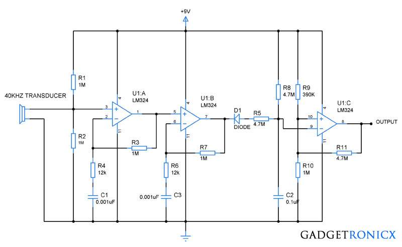
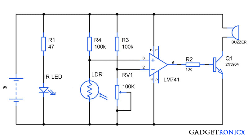
This circuit uses a simple ultrasonic receiver ( transducer) which converts the incoming ultrasonic wave to equivalent voltage. The signal was then passed through a non inverting amplifier built using Quad Op amp IC LM324. The gain of the amplifier can be controlled using a feedback resistor R3 connected from output to the inverting terminal.
Then this signal is further passed to the next stage of non inverting amplifier. There the signal was further amplified and the output was obtained from the pin 7 of the LM324 IC . The signal is then rectified using a diode and passed through a Resistor R5 and Capacitor C2 to prevent the false triggering in the output.
Final stage of the op amp was wired as an comparator which gives high output when ever a ultrasonic wave is detected by the transducer and low signal whenever there is no wave detected by the transducer.
This circuit along with the transmitter can be used to build simple robots in which it will assist the robot to evade the obstacles lying ahead them. Also can be used in range detection when used with a Microcontroller.
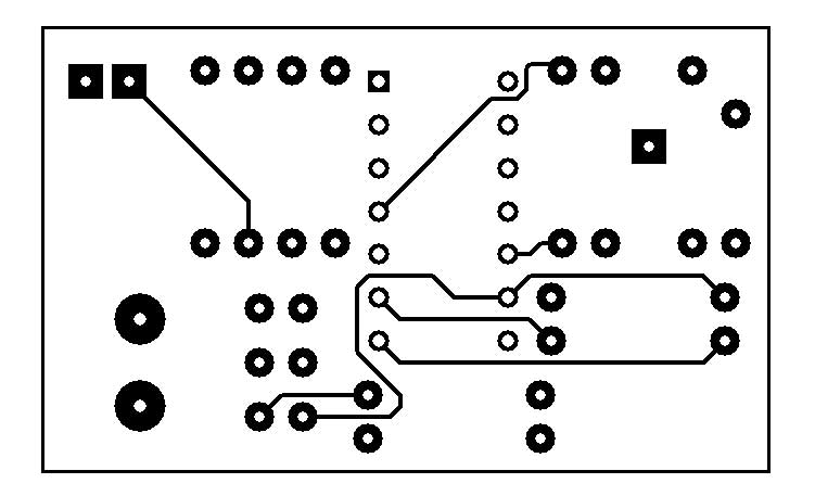
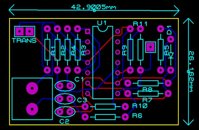
PCB DESIGN:
|
|
 |
| TOP VIEW |


The circuit is working if I applied the input signal from signal generator, but it is not working if the signal was received by an ultrasonic transducer, does anyone know why?
Hi i make the circuit.
Whats the story off the output wire?
Dose it goes to a speaker or headphone or input of amplifier or sonething else ?
Thanks
Why you used tow opamp and why you used a comparator?
Hi sir,
what should has change in the circuit when we are using 400khz transducer.
please share the link for the transmitter circuit
Hi Sir! Did you test this circuit in real time and did it work? Also, what is the gain of this two-stage op amp?
Hi Sir!
I just want to ask, have you tried this circuit? Did it work?
I saw your transmitter circuit as well. Together, how can it measure distance?
How can I buy your readymade project of ultrasonic transmitter and receiver circuit ?
Vasanth,
We don’t have this project ready made, you have to build for yourself!
I simulated the circuit on proteus using a pulse input, didn’t work.
Seeka,
Simulations are not correct always. try this circuit out in real time