Two digit Counter Circuit can be seen in hospitals, banks etc for the purpose of counting any process. You might have seen the Single Digit Counter Circuit using 7 segment in our site and this is just an expanded version of the single digit counter. Here we are employing two 7 segments and two IC 4026 a seven segment Display Decade counter. And a IC 555 to feed the required pulse to the decade IC’s used in the above circuit. The whole circuit was designed to increment the count with a single push button switch. Lets move into the working of this counter circuit.
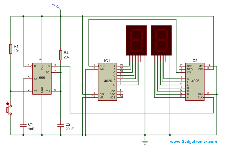
CIRCUIT DIAGRAM:
WORKING OF TWO DIGIT COUNTER CIRCUIT:
The working of the above circuit starts with the 555 where it was wired as a monostable Multivibrator. The important characterstics of a Monostable Multivibrator is as long as the pin 2 receives a positive trigger the output at pin 3 will be of low state. And when negative trigger was fed into the pin 2, the output at the pin 3 will go high for a specific period of time. This time was decided by the Resistor R2 and Capacitor C2 connected along with it. This timing is necessary to offer the debouncing delay to the circuit in order to avoid multiple input pulses at the same time to the trigger input. The equation governing the time period is given by T= 1.1 x R x C.
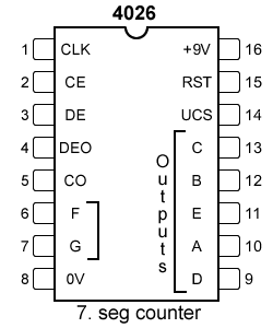
IC 4026 is a seven segment display decade counter which is used to drive a 7 segment display with input clock pulse. Here the clock pulse was obtained from the monostable multivibrator and fed into the pin 1 of the IC2 4026 since count value should be started from the 7 segment which is placed right hand side. Pin 2 was usually grounded since giving high signal to this pin will inhibit the input clock signal to pin 1. Pin 3 was meant for enabling the display and it was given high signal in both of the 4026 IC’s. The 4th pin was meant for enabling carry out and we left this pin unconnected and the same case applies to pin 14th of the 4026 IC.
Initially when the circuit is switched ON the 7 segments will indicate “00” count and as soon as the negative trigger was given to 555 high pulse will be obtained from pin 3. The high pulse was fed to IC2 and therefore it increments its count with each button press displaying 1,2,….9 in its seven segment. As soon as 10 counts was incremented by IC2 a high to low signal was obtained from its pin 5 which indicates the completion of ten increments.
The pin 5 of IC2 was connected to the CLK pin of the IC1. Therefore whenever 10 counts was completed by the 7 segment at the right side, the high to low signal at the pin 5 will feed a single clock pulse input to the IC1 and therefore the corresponding 7 segment will be incremented one value. In the same manner IC2 will count from 0 to 9 and then value in the IC1 will be incremented by one. Thus this counter circuit is capable of counting upto 99 and then returns to zero.
NOTE:
- Each push button switch differs in properties so as their debounce delay, so if you face problem in multiple increments of 7 segment values increase the values of Resistor R2 and Capacitor C2.
- If you want your circuit to automatically count the values, then replace the Monostable Multivibrator with Astable Multivibrator with assigned time period.

Sir what changes have to be made to make it work on its own by just giving a pulse?
Aditya,
Remove the button and R1 resistor. Feed the pulse into the Trigger pin 2nd of IC 555
Sir, please help me.i want to add a buzzer at a specific limit. How can i do that??.for e.g. when it comes to the count of 20 buzzer work.
Please reply ..
Iqra,
There are many number of ways you could do that. First use an MCU replacing all the chips that will be so plain and simple. Next if you have a 4017 chip add it along with the circuit. Take the CO output from IC2 and feed it to the CLK pin of 4017. Connect a buzzer with Output 1 pin of 4017 you will get what you need. Note you should add some switching elements like transistor to use along with buzzer as output current from 4017 is too less to drive buzzer.
i want to connect infrared sensor instead of push button….can you send me its diagram…
Asad,
Simple! replace the button with a IR sensor and feed its output to the trigger input of 555. But keep in mind that 555 monostable mode will give high output when trigger input is low. You may want to set it up that way
Can you link the PCB design of this circuit
Hi Troy,
Haven’t designed one added to my To do’s will post it here once its done.
Sir, could you please show me a version of this circuit that has a button if pushed decreases count on the display. Thanks 🙂
Dennis,
I believe you need to use MCU for that.
Hi I would like to create a 3 7 segments displays with increase and decrease buttons
could help me to do that ??
Aimen,
Of course i can, please start with the design and coding. Write to me if you got stuck i will help you.
Can I replace the seven segment display with a series of LED’s ?
Thank you 🙂
Sure you can 🙂
Sir,could you please show me shcematic diagram with single 7 display work ic 4026 and 555 timer and also reset pause switch?
Martiyana,
This is a counter which increases counts only when you press the button connected to IC 555. So there is no need for pause button here. Regarding the single display you can remove the IC1 and use only IC 555 and IC2. For reset just turn on and off the whole circuit it will be your reset. If you are looking for stopwatch refer this link
https://www.gadgetronicx.com/diy-stopwatch-digital-ic-4026-4017/
Sir is the seven segment a common anode or a common cathode?
Jasper,
Its common cathode.
I followed the circuit diagram above but my counter does not increment to 1 when I push the button, it just displays ’00’, can you please help me figure out the probem?
Tenshi,
Am not sure where the problem lies the circuit should work. Try testing the circuit in splitting into two parts test the 555 monostable multivibrator first then try the counter part using IC 4026. This will help you out in rectifying the problem.
Tried it too. I have the same problem.
Hi,
Have you tried the above suggestion?
Can you supply a parts list for this counter circuit? Was also wondering if C2 was correct at 20uf?
Rick,
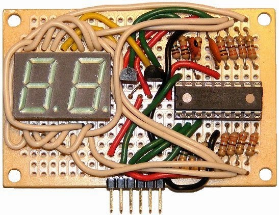
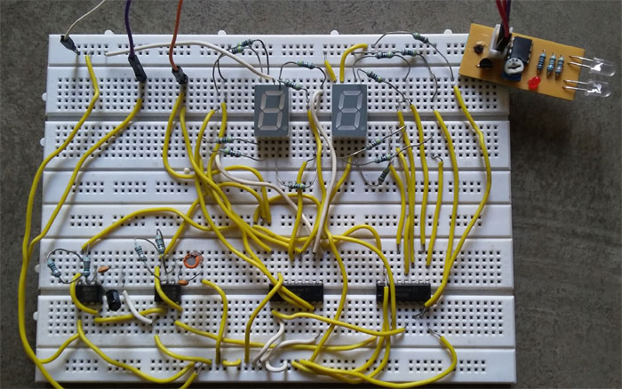
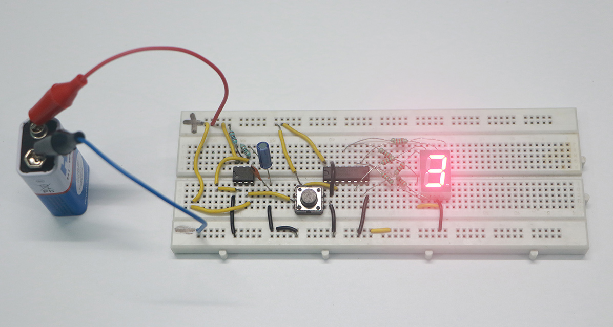
Please ignore the above assembled circuit it was just for illustration. Yes the circuit diagram and the C2 values was correct. You can try out the alternative of this one here https://www.gadgetronicx.com/people-object-counter-circuit-diagram-ic555/