Today we are in a world where robbery has increased to a great extent. Hence there is a need to protect everything using a security system. Here is a small project on security system called ULTRA SECURITY SYSTEM which will be very useful.
This system is three way protected and consists of three sensors which will alert the user in case if any attempt to breach occurs. For simplification i have explained the three parts of this Ultra security system individually. Let’s see what is that three level security
1) LDR AND LASER LEVEL IN ULTRA SECURITY SYSTEM:
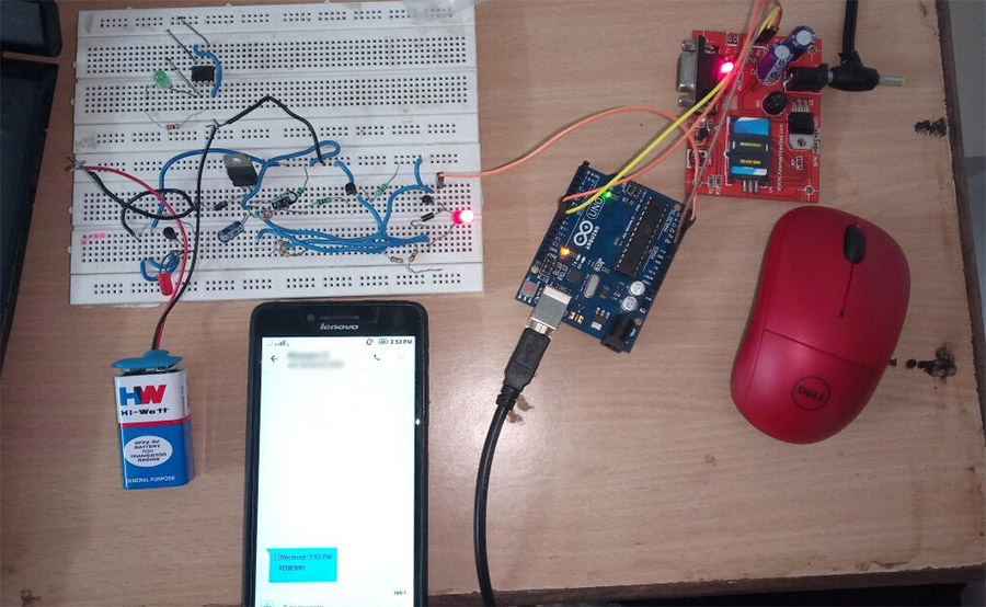
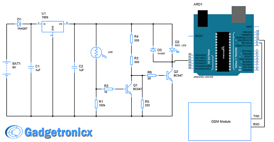
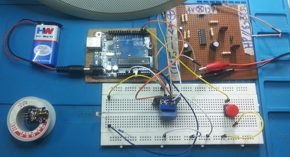
This is the first level of detecting the robbery in BANK. LDR sensor is placed inside the locker the laser is focused on the door of the locker, When the robber tries to open the BANK cell the LDR in locker is light deviates and then the Arduino commands the GSM module then this sends a text message “ROBBERY” to the registered mobile number or the nearest police station.
1.1) COMPONENTS USED:
- LDR
- ARDUINO
- GSM Module
- NPN Transistors BC 547
- Diodes (1N 4007)
- Red LED
- Capacitors (1 uF)
- Voltage Regulator(7805)
- Resistors
- Batteries (9V)
1.2) SCHEMATIC CIRCUIT:
CODE:
#include <SoftwareSerial.h>
SoftwareSerial mySerial(9,10); //(tx,rx) aurdino
float a=A2;
int b,c;
void setup()
{
  mySerial.begin(9600);   // Setting the baud rate of GSM Module
  Serial.begin(9600);    // Setting the baud rate of Serial Monitor
  delay(100);
}
void loop()
{
  b=analogRead(a);
  c=map(b,0,1023,0,10);
  Serial.print(c);
   Serial.print("/");
  delay(1000);
  if(c<3)
  {
        mySerial.println("AT+CMGF=1");    //Sets the GSM Module in Text Mode
        delay(1000);  // Delay of 1000 milli seconds or 1 second
        mySerial.println("AT+CMGS=\"+918500911427\"\r");
        delay(1000);
        Serial.print("ROBERRY");
        mySerial.println("ROBERRY");
        delay(100);
        mySerial.println((char)26);// ASCII code of CTRL+Z
        delay(1000);
  }
}
2) LM35 LEVEL:
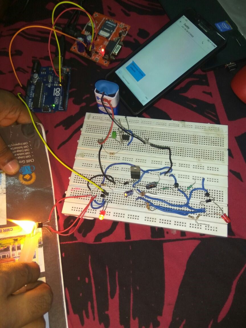
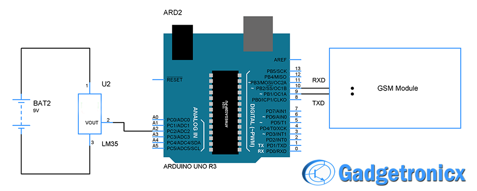
In this method if the robber tries to open the door by using any heating device like flame thrower. This LM35 heat sensor detects the heat and sends the message with the help of Arduino. It sends the command to the gsm module which will further send a text message as “ROBBERY” on the registered mobile number or if it can be contact to nearest police station.
2.1) COMPONENTS USED:
- Arduino Uno
- GSM Module
- LM35 Sensor
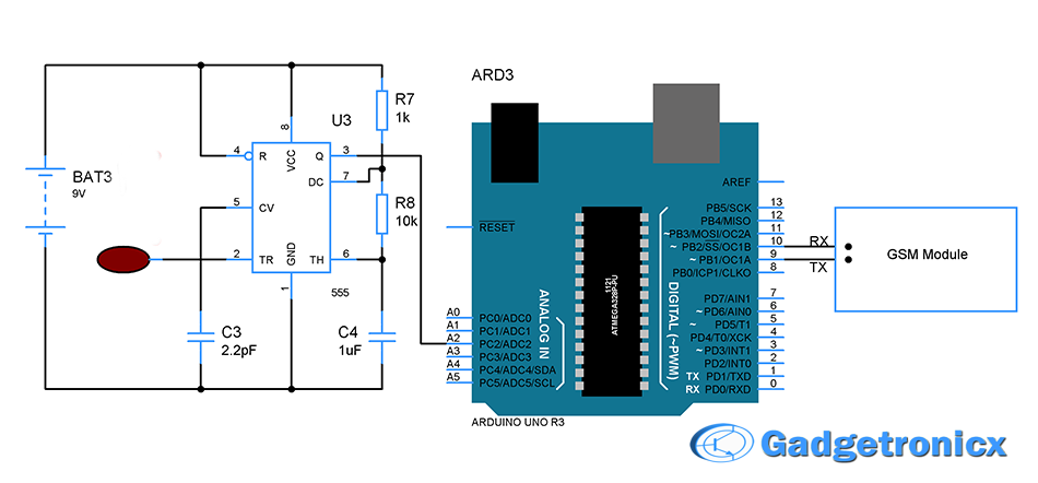
2.2) SCHEMATIC CIRCUIT:
2.3) CODE:
#include <SoftwareSerial.h>
SoftwareSerial mySerial(9,10); //(tx,rx) aurdino
float a=A2;
int b,c;
void setup()
{
  mySerial.begin(9600);   // Setting the baud rate of GSM Module
  Serial.begin(9600);    // Setting the baud rate of Serial Monitor
  delay(100);
}
void loop()
{
  b=analogRead(a);
  c=map(b,0,1023,0,10);
  Serial.print(c);
   Serial.print("/");
  delay(1000);
  if(c<8)
  {
        mySerial.println("AT+CMGF=1");    //Sets the GSM Module in Text Mode
        delay(1000);  // Delay of 1000 milli seconds or 1 second
        mySerial.println("AT+CMGS=\"+918500911427\"\r");
        delay(1000);
        Serial.print("ROBERRY");
        mySerial.println("ROBERRY");
        delay(100);
        mySerial.println((char)26);// ASCII code of CTRL+Z
        delay(1000);
  }
}
3) TOUCH SENSOR:
This type of method is also used in detecting the robbery. This sensor works when a robber tries to open the door of locker by touching the handle. The touch pad on the handle will signal Arduino which in turn sends the command to gsm module. GSM then forwards a text message “ROBBERY” to the registered mobile number or nearest police station.
3.1) COMPONENTS USED:
- Arduino
- GSM Module
- NE555
- Resistors
- Capacitors
- Touch Panel
3.2) SCHEMATIC CIRCUIT:
3.3) CODE:
#include <SoftwareSerial.h>
SoftwareSerial mySerial(9,10); //(tx,rx) aurdino
float a=A2;
int b,c;
void setup()
{
  mySerial.begin(9600);   // Setting the baud rate of GSM Module
  Serial.begin(9600);    // Setting the baud rate of Serial Monitor
  delay(100);
}
void loop()
{
  b=analogRead(a);
  c=map(b,0,1023,0,10);
  Serial.print(c);
   Serial.print("/");
  delay(1000);
  if(c>30)
  {
        mySerial.println("AT+CMGF=1");    //Sets the GSM Module in Text Mode
        delay(1000);  // Delay of 1000 milli seconds or 1 second
        mySerial.println("AT+CMGS=\"+918500911427\"\r");
        delay(1000);
        Serial.print("ROBERRY");
        mySerial.println("ROBERRY");
        delay(100);
        mySerial.println((char)26);// ASCII code of CTRL+Z
        delay(1000);
  }
}
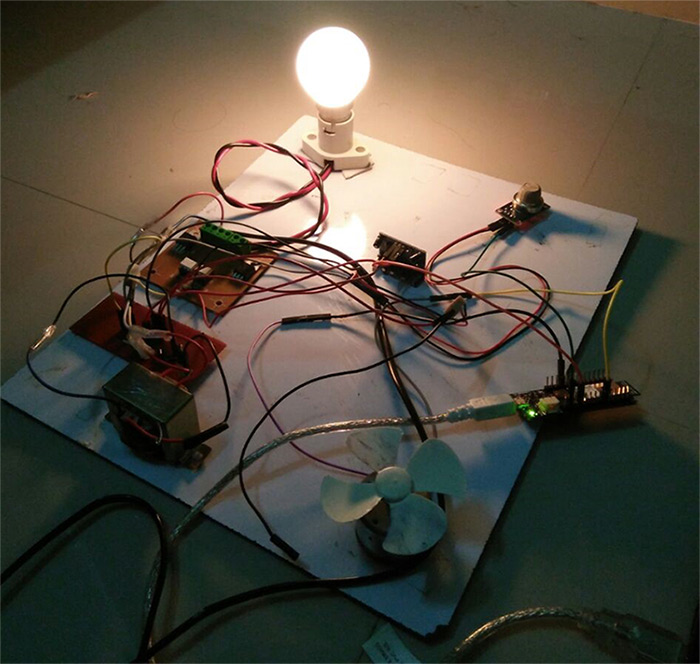
These three levels when combined together will form the three layer ultra security system. Combining these three features shouldn’t be a challenge we just need to assign dedicated analog pins for each sensor and force Arduino to monitor them repeatedly. Hope you liked this project, do try it 🙂
MAKERS:

- Rajesh
- Bhargavi
- Mehul shah
- Venkata Krishna


Pingback: Three level Ultra security system using Arduino • Tech Projects