Temperature sensor circuit can be used to detect any raise or fall of temperature in the atmosphere and can be employed for the purpose of monitoring. This temperature relay controller circuit can be used to detect the temperature change and use that signal to activate the relay which provides room for the users to activate any device of their desire. Summing up this electronic circuit is capable of sensing the temperature change and also activates the external device connected to the relay.
WORKING OF CIRCUIT:
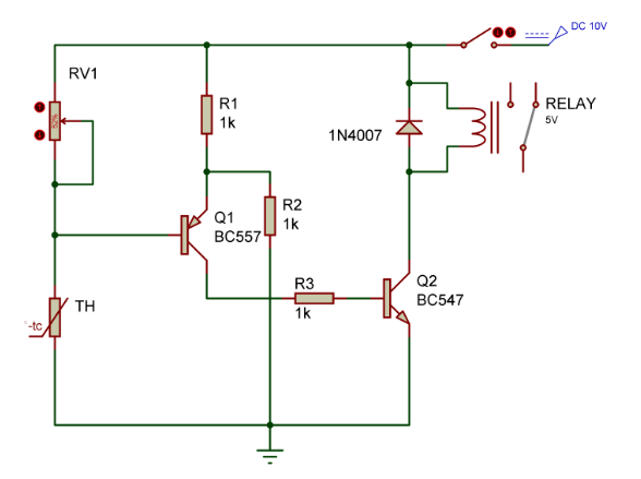
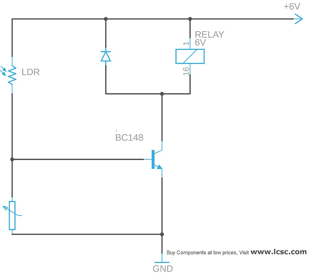
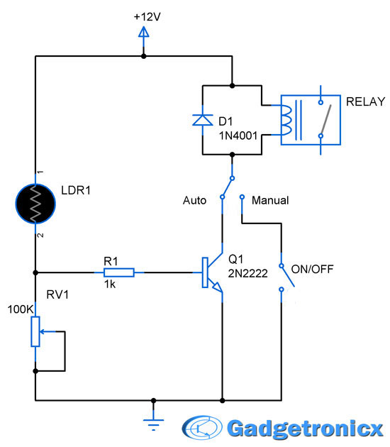
In the above diagram a thermistor (TH) was used to detect the change in the external temperature. A variable resistor RV1 was used to alter the resistance so that the transistor Q1’s base voltage is 0.5v smaller than the emitter voltage at a point where the temperature is lower than the desired triggering or switching temperature. Now the rest of the operation is plain and simple as it looks in the above temperature sensor circuit.
When there is a rise in temperature Q1 and Q2 start conducting and the relay will be switched ON. Thus the temperature dependent relay switching is done using this simple circuit. A protection diode 1N4007 was added to prevent the circuit from damage due to the backward current after the relay switched off. The value of RV1 must be chosen based on the NTC thermistor used. The relay can be turned off by opening the switch providing connection to the supply. The circuit can also be modified as cold relay or to detect a reduced temperature limit by interchanging the places of TH and RV1.


Hi, I found your post on google+ group “Electronics” , I really appreciate your post and design. I have a better design about this. are you interested in it?
Great, could you tell me? I just prepared to buy newsmartcom Electronic Components and start to design one. Any further discussion?
Andy,
Of course, i am definitely interested. mind sending the design ?