 |
| Temperature Controlled DC motor |
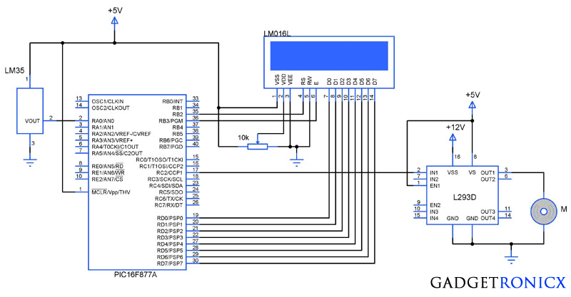
You might have come across several applications where we need to control a specific device based on analog parameter. This Embedded system works in a similar concept where we are about to control the speed of a DC motor using based on the external temperature. The rise in temperature will result in increase in speed of the motor and vice versa. These type of Temperature controlled fan systems can generally be used to maintain temperature of a room or object automatically.
DESIGN OF TEMPERATURE CONTROLLED FAN SYSTEM:
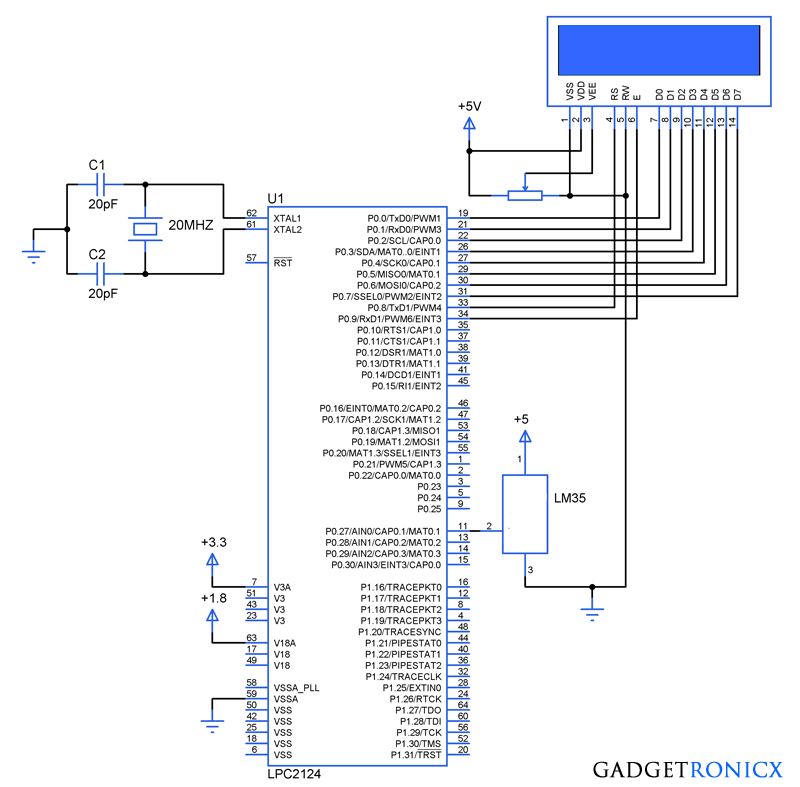
- The temperature is measured by means of a temperature sensor LM35.
- The output voltage of the sensor is fed to the A/D channel of the Microcontroller.
- Based on the sensed temperature the speed of the motor is controlled using PWM .
- Several temperature ranges was set in the code to vary the motor speed based on the level of temperature sensed.
- The speed of the motor is controlled by using PWM.
- The motor is driven using a driver IC l293D, See a brief explanation on its working and wiring here.
LM35:
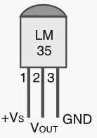 |
| LM35 Pin Diagram |
Lm 35 is used to sense the external temperature which is capable of sensing temperature ranges from -55 to 150 C. The output voltage is proportional to the temperature hence there is no need of trimmers to calibrate the reading. The output voltage of this sensor varies by 10mv per degree change in temperature.
CALIBRATION:
We are using a 10 bit ADC and Vcc as Vref to the ADC module of the Controller. So in order to determine the step size we have to divide the Vref by our resolution that is 2^10 ( 1024 ).
Step Size = 5 / 1024 = 4.83mV
We obtain a change of 10mV with each rise or fall in temperature from the sensor. And value in the ADC register will alter by two steps with each degree change in the sensor since two increments of step size i.e 4.833mV * 2 = 9.96mV which is approximately equal to 10mV. So in order to obtain the original value we have to divide the contents in the ADC register by 2
Real value = ADC value / 2
CODE:
This code was built using CCS compiler for PIC Microcontrollers.
#include <16F877A.h>
#device ADC=10                              //Setting ADC bits
#FUSES NOWDT
#FUSES NOBROWNOUT
#FUSES NOLVP
#use delay(crystal=20000000)
#byte lcd=0x08
#byte TRIS_lcd=0x88
#bit rs=0x06.2
#bit en=0x06.3
#bit TRIS_rs=0x86.2
#bit TRIS_en=0x86.3
long int adc_value,real_value;
int i;
char value[4];
unsigned char text[]="Temperature:";
void display(unsigned char a, int b);
void motor();
void main()
{
  TRIS_lcd=TRIS_rs=TRIS_en=0;
  display(0x38,0);
  display(0x01,0);
  display(0x0c,0);
    for(i=0;i<=12;i++)
    {
     display(text[i],1);
    }
  setup_timer_2(T2_DIV_BY_16,255,1);    //Setting timers for PWM
  SETUP_ADC_PORTS(AN0);                   //Setting ADC PORTS
  SET_ADC_CHANNEL(0);                       //Selecting Channel
  SETUP_ADC(ADC_CLOCK_INTERNAL);
     while(TRUE)
      {
        delay_us(20);
        adc_value=READ_ADC();            //Reading ADC value
        delay_us(10);
        real_value=adc_value/2;           //Obtaining real value
        motor();
        sprintf(value,"%lu",real_value);  //Changing int to char
        display(0x8c,0);
          for(i=0;i<=3;i++)
           {
             display(value[i],1);
           }
      }
 }
void display(unsigned char a,int b)         //LCD sub routine
  {
    lcd=a;
    rs=b;
    en=1;
    delay_ms(10);
    en=0;
    delay_ms(10);
  }

void motor()
{
  if(real_value<10)
   {
   setup_ccp1(CCP_OFF);
   }
  if(real_value>10)
   {
     setup_ccp1(CCP_PWM);
      if(real_value>=10&&real_value<=29)
      {
        set_pwm1_duty((int16)204);         //20% duty cycle PWM
      }
      else if(real_value>=30&&real_value<=69)
     {
       set_pwm1_duty((int16)510);         //50% duty cycle PWM
      }
      else if(real_value>=70&&real_value<=99)
      {
         set_pwm1_duty((int16)715);      //70% duty cycle PWM
       }
      else if(real_value>=100&&real_value<=150)
       {
         set_pwm1_duty((int16)919);     //90% duty cycle PWM
       }
    }
 }
The above code uses built in functions in the CCS compiler to use the A/D and PWM feature in the Microcontroller. The received analog value is calibrated to display the temperature in the LCD. The “real_value” int value is converted to character using “sprintf” in order to display the temperature values.
The temperature ranges and duty cycle of the PWM is given using the subroutine “.motor”. So the microcontroller runs a check on the temperature every time and alters the speed of the motor based on it.

sorry i meant IC L293D not IC1293D.
nice one,the world needs more people like you to be a better place. when i ran the simulation on proteus, the LCD worked fine but the motor didn’t move. can you help me with a possible solution and explanation of the wiring and operation of the IC1293D motor driver, the link provided above on this page leads to an empty page. also i need to implement this circuit on a varro board, would i need to make any adjustments? please i urgently need your assistance today. thanks
Dave,
Post updated with the valid link now, thank you letting us know about it. You will find the instructions on working with L293D for driving motor. Do check that in your simulation you have changed the temperature value greater than 10 degrees. I have coded it in such a way that motor will only start move after the temperature reaches 10 degree mark.
Can we use pic18 instead of pic16?
Durga,
Yes you can.
hi, when i run this code on proteus 8, it shows the following errors:
1.no power supply specified for net 5V in Power Rail Configuration.
2.no power supply specified for net 12V in Power Rail Configuration.
3.simulation FAILED due to netlist compiler error.
i used MPLAB IDE and ccs compiler too. what should i do? please help.
Sathish,
Try giving +5 and +12 in the power pins.
So would it be fine to use MPLAB IDE 8.5 software? tried running this code using ccs compiler plug-in thru MPLAB and it didnt work tho :< too many errors. Im guessing its about the header file? I hope you could answer soon. Thank you btw, for sharing this with us 🙂
Mae,
Well am not too sure about running the code in MPLAB. The above code was built and tested in CCS compiler i would suggest you to try it out in CCS compiler.
pls sir, can you help me with the coding in mikro c environment, i am working on the same project but i dont have a ccss compiler. i only have mikro c and code block. help me out
Hi Kassam,
Sorry but I don’t time to rebuild this in MikroC kindly try and get the CCS compiler and try it out. Don’t take it as an offence 🙂
Do you have the code to be used in MPLAB IDE software ?
I can just see squares on LCD, Im sure that connections are correct. Do you think why?
Sercan,
Adjust the contrast voltage using a POT to the pin 2 VDD of the LCD, that might be the problem i guess.
hello,help program I get an error when creating the hex file Can you
Turan,
Which compiler you are using?
The oscillator must connect between 13.-14. pins, right? And what is the meaning of “#use delay(crystal=20000000)” on codes?
Sercan,
Yes the oscillator should be connected to the pins 13 and 14. And that line was used in CCS compiler which says that delay function was based on 20Mhz crystal. That is all delay values should consider the usage of oscillator frequency 20Mhz. Checked my hard drive a moment back and i realized i have only tested this project in simulation level and last time you asked i answered it as 8Mhz after seeing my Dev board!!! err my bad. Since its been long time i posted this i really haven’t remember about testing this one. Anyway i hope you got the meaning of that line in code, you can change the value based on the crystal you are gonna use.
you mean i need to change the oscillator value 8Mhz instead of 20 on code?. Cause i used 8 mhz on board.
and does it matter which oscillator i used, 8 or 20mhz? Thanks a lot btw :
)
Sercan,
Yes you need to alter the value from 20 to 8mhz in the code. Of course you can use 8Mhz crystal in the board. Yes the crystal speed matters sometimes but not much in this project. The crystal speed affects the rate the controller executes the instruction and other functions happening inside the registers of the controller. Your 8mhz will do the job just fine.
Can you tell me the oscillator you used, its 20 MHZ?
Sercan,
It was 8Mhz.
why the coding cannot build or run with MicroC pro software?
Amira,
Beacause this code was built using CCS compiler and not MikroC.
Great project i was exactly seeking for this one. i was wondering if can you help me with slight modification of the above project . the above design and code controls a single motor based on the external sensed temperature, what if i need to add another motor to the design and control it when temperature breached a particular level?
By my understanding you want additional motor to be controlled by the controller when the temperature exceeds certain range. In that case you have to add an extra motor to the IC L293D and Control it through the pin CCP2 of the Microcontroller. There wont be a major modification in the code all you need to do is add the setup_ccp2 & set_pwm2_duty to the code and don’t forget to include all these inside the conditions of your temperature level. Hope you understand it, if not feel free to ask me