 |
| Source : EFY |
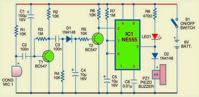
Sensor circuits are widely available and are of several types each possessing significant uses. The above sound sensor alarm circuit is one of that kind where it was used to detect the sound signals in the environment. Here a microphone was used as a transducer to convert sound signal to electrical signal and in addition a 555 IC was used to ring alarm when a sound or noise in the environment is detected.
WORKING OF SOUND SENSOR ALARM CIRCUIT:
The working of the above circuit starts with turning on the switch S1 and there a LED was added to indicate that the circuit is ready to work. Initially in the absence of sound there will be no electrical signal obtained from the condenser microphone. Whenever the Microphone detects a sound in the environment , it gives the electrical signal which was fed into the Transistor T1 for the purpose of amplification.
The amplified signals obtained from the collector of the transistor was then fed into the base of the Transistor T2 through capacitor, diode and resistor. The Transistor T2 was wired to work as a switch in the above circuit ,so whenever a signal reaches the base of T2 current flow will takes place from the collector to emitter of the Transistor T2.
In this circuit NE 555 was wired as a monostable multivibrator in which a negative trigger to the pin 2 of the IC gives out high signal and positive trigger gives low signal in the output, read detailed description working of 555 Monostable mutivibrator . So when the transistor T2 is switched on by the incoming signal, it permits current flow from C to E thereby giving a negative trigger to the NE 555. The negative trigger in turn changes the output of IC1 to high state powering the Piezo buzzer to produce sound for fixed duration. The duration was decided by means of R and C values connected to the IC 555. The time duration was given by the formula
T=1.1 x R x C
Connecting relays at the pin 3 of the IC will enable you to drive high loads and this could allow the above circuit to be used as sound or noise sensor.




Sir in my company we don’t have feedback transformer so I want to design a circuit that sound alarms went power transformer hum due to supply of light thanks
and what sort of noise does this circuit detect?
sir,what is the cost of microphone used here?
Sir,what are the existing of this syestem
Sir,I want to know some literature reviews of sound sensor alarm
May i know the PCB design in this circuit? Thanks..
Hi Arnold,
Will work on it and let you know.
Thank you very much Sir.
Sir any update? Thanks.
Arnold,
It might take some time, kindly be patient.
Hi this is Jigar.
I want to use this with radio. But alarm circuit should activate when there is no sound come from radio. Can we use this circuit?
Please suggest.
Hi Jigar,
Yes you can use this circuit for that but you need to do minor changes for that to work the way you described. Remove R8, D2 and LED1 from the circuit and use PNP transistor at the output of 555 and drive buzzer using it.
Test your circuit and keep posted the outcome.
Please tell me value of PNP transistor. or can i use BC547?
Jigar,
Bc547 is NPN transistor.. use BC557
sir,i want a circuit which sense cry of a baby and gives output as a song.pls help me..shahadv007@gmail.com this is ma ID
they not work what is problem
Amir,
Narrate your problem.
sir i need circuit of 555 to produce noise can u help me my mail id is praveenchandar5@gmail.com
Noise what sort of noise? if you just want to produce a clicking sound just make a astable multivibrator using 555 and feed its output to a buzzer or speaker.
555 is precise timer. For noise is not good. You can make many thing with it but not noise.