 |
| Solar Powered Battery Charger Circuit |
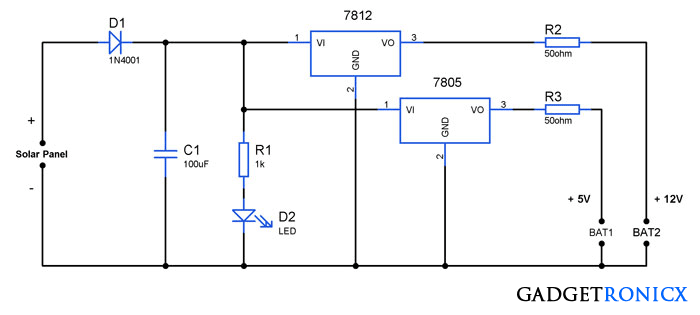
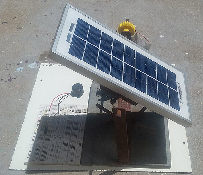
Solar power is one of the free form of renewable energy that our planet earth is blessed with. Increase in energy demands forced to seek ways for extracting power from renewable sources and solar seems to be a promising source. The above circuit will demonstrate how to build a multipurpose battery charger circuit by means of a simple solar panel.
WORKING OF SOLAR POWERED BATTERY CHARGER CIRCUIT:
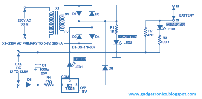
This circuit derives power from a 12V, 5Watt solar panel which converts the incident light energy to electrical energy. A diode 1N4001 was added to prevent the reverse flow of current which could result in damage of the solar panel.
A led was added with current limiting resistor R1 to indicate the flow of current. Then comes the easy part of the circuit, voltage regulators was added to regulate the voltage and to obtain desired voltage levels. IC 7805 gives 5V as output whereas IC 7812 gives 12 voltage as output.
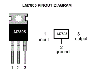 |
| IC 7805 Pin diagram |
Resistors R2 and R3 are used to restrict the charging current to a safer level. You can charge NiMh, Lithium ion batteries using the above circuit. You can also use additional voltage regulators IC along with it to obtain different output voltage levels.



I HAD 23 V DC SOLAR PANEL AND I COONET TO DIRECTY 12 V BATTERY SO WHICH VOLTAGE REGULATOR USE AND IT IS POSSIBLE OR NOT,
You should use a voltage regulator. 23v panel should be able to charge a 12v battery under optimal sunny conditions. Although you should check for the charging voltage of your battery ( you can find that in its datasheet ) and regulate the voltage to that from the panel.
1) At least 14V solar panel needed in order to get 12Vout from 7812. So 12V solar panel is useless.
2) You can’t charge(or you shouldn’t charge) a lithium ion battery. With 7805.
3) You should calculate the power dissipation on resistors so people can take their components by considering them.
Thanks.
Can you elaborate on 1 and 2
nice
when we remove resister what will doo
Ali,
Couldn’t get your question.