 |
| Solar powered garden lights |
Solar power attained a great significance after increase in energy demand in our daily life. To conserve power we need to utilize all the natural sources we can to extract power. This forces us to use solar energy to power the lights and other appliances in many places. This solar garden lights circuit will help you to build a Simple Solar powered garden LED lights.
WORKING OF SOLAR GARDEN LIGHTS CIRCUIT:
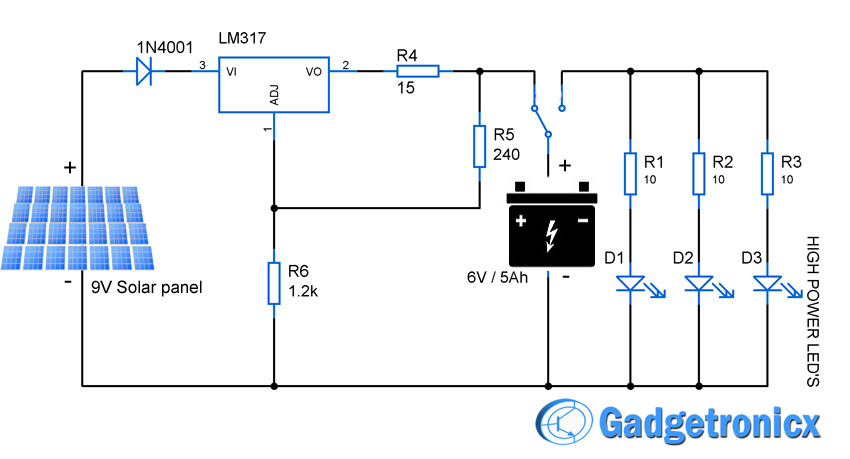
Solar panel forms the backbone of the above circuit. The above circuit can be classified into two sections Charging section (From Panel to battery) and Lighting section (From battery to LED’s). The Charging section serves the purpose of charging the battery whereas Lighting section powers up the LED’s connected to it.
CHARGING SECTION:
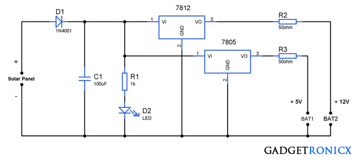
The above circuit uses a solar panel rated 16v/5w to charge the battery during day time. A voltage regulator was used to regulate the voltage flow to the battery to avoid fluctuations in the voltage level from panel to battery. An LED was added to indicate the charging of the battery and Diode D1 to avoid panel damage from reverse flow of current during night time.
LIGHTING SECTION:
The Battery is the first thing to consider in the lighting section. This circuit uses a 12v/1Ah (1 ampere current for 1 hour) rated Lead Acid battery to power the whole lighting section. We should ensure that the load didn’t draw more current than the specification since it may make the battery dead by draining the charge completely.. A switch was used here to turn the loads on and off by the user.
White LED’s are chosen here to do the lighting job in the above circuit since it possess high luminosity and light efficiency. White LED’s drop 3-3.5 v and consumes 30mA for working. The Resistors R3,R4….R7 act as current limiters to prevent the damage of the LED’s.Now we know both the specification of the battery and LED’s used. So lets do some math to calculate the amount of LED’s that battery can lighten for the required time period.
This Lead Acid battery can provide 1 ampere current for one hour period. We are here using 15 LED’s of five parallel sets in which they are connected in series. We all knew that current through a series connection will be same so summing up the current consumption for 15 LED’s as per the above connection we obtain
30mA x 5 = 150mA
Since battery rated 1Ah it can source power to our lighting section for
Battery Source period = 1000mA / 150mA = 6.6 hours
So the battery can source the above 15 LED’s around 6 and half hours when its fully charged. But for efficient and long lasting functioning of a battery you must use only 80% of its charge. Hence in the above circuit battery should be used only 5 continuous hours before recharging it for efficient usage.
NOTE:
- You can use other rechargeable batteries in this purpose after calculating load current and the time period your battery can source the load.
- The count of LED’s can also be increased but make sure your battery source is robust enough to source the LED’s for required time period.
UPDATE:
The Solar panel used to power the circuit was modified to 16v/5W instead of 12V/5W since the 12V panel cannot source sufficient voltage to charge the battery due to the voltage drops by the diode and 7812 IC. If you are intend to use 12V panel itself then kindly replace the 7812 linear regulator IC with Step up Voltage regulator which is capable of providing 12v as output in spite of voltage drops in input.



I am interested in the solar charger light circuit. I notice it has the charger circuit + plus light with a relay that is what I want but: where is the coil of the relay connected? please clarify that for me so I can build it.
Karel,
I believe you are referring to the switch that is used after the battery. It is not a relay but a switch to activate the LEDs connected to the battery
In addition to comments from others, I would like to mention that for getting maximum power from the soler panels you would need MPPT device, which is microcontroller-driven device optimizing voltage-current ratio. Regulators work, they are just not as efficient as MPPTs.
Sorry for the comment box in this site and its the first time i have received a complaint regarding it. I will certainly look into it.
I agree with all your suggestions and i want to thank you for pointing the errors out frankly. Usage of switching regulators will be a great idea but cost would be a big factor when comes to those kind of regulators while 7812 will come at cheap cost. And in the lightning section the resistors are used for limiting current to prevent damage of the led so i guess it must be there.
You have a point even though your comment seems bit rude and thanks anyway for pointing out the flaws.
I guess you don’t get it – you cannot use the 7812 and expect to charge a twelve-volt lead acid battery. It is not an acceptable circuit. When the charge voltage on a lead acid battery reaches 12.0 volts, you have only charged it to less that 50% of its capacity. A 12-volt lead acid battery is considered discharged when it drops to 11.8 volts. You are only exceeding this by 200 millivolts. If you look at the charge curves or tables on reputable websites, you will see that you are actually charging to somewhere between 25% and less than 50%.
And, the resistors are not needed, since a more elegant solution is available. A resistor in series with a LED string will limit the current, and provide a functional circuit, but it is a tinkerer’s circuit. Simply purchase some LED drivers. You can get some very cheap LED drivers now. They have been on the market for many years, and as all electronics parts do, they have become more sophisticated at a lower cost… you can get one where you will need a minimal number of parts added to make it functional.
I may seem a bit rude, but this is the real world out here. If someone believed that this was a good way to implement this function, and actually bet their product on it, they will have been done a great dis-service. I don’t know what college you went to, or are going to, but trust me, your professors would not tolerate this.
Okay, I will comment no more – either you get “it”, or you are doomed to having a tinkerer’s site where you lead even children astray.
The sooner you are exposed to these realities of life, the easier you life will be. Of course, “You must first recognize reality” Yes, it is a quote…
This blog on your website, has a serious flaw – Any comment that is entered is erased and is not recoverable when a selection is made in the box below the comment box that designates which name the comment is to be published under. The comment has to be typed into the comment box a second time.
Your circuit would quickly get a failing grade in my electronics class:
First, you are charging a lead acid battery that is nominally called a twelve volt battery, through a 12 volt regulator. This limits the charge on the battery to 12.0 volts, which will charge the battery to less than 50% of it’s capacity. Check the Charge curve for a 12 volt lead acid battery – wiki probably has a rudimentary overview which will be sufficient to support this discussion.
Second, you do not need a polarity reversal protection diode in a hard wired or connector protected circuit such as yours. This diode is only used in circuits where the batteries that power a circuit can be installed backwards. This diode is wasting about 5% of all the energy you gather with your solar cells.
Third, the resistors in the charge circuit and the LED drive circuit are a super waste of power. Use switching regulators in both cases. These resistors are wasting much more power than the diode I discussed above.
Unfortunately, I really cannot find anything about this circuit that is good. I didn’t read much of your text, since it would be a waste of my time reading text that supports a circuit that very poor.
Indeed, I have been critical here, and I intended to be. You really need to do a much better job at this. You are posting circuits on a site that others will assume is well thought out, and provides a good source for design examples. This is a serious dis-service to anyone visiting your site. If you post something technical, you have the responsibility to make it the best post possible. As I stated above, this post would get you a failing grade in my electronics class, and if it was part of a job interview, you certainly would not get the job – even if you were the only applicant…
The garden solar light circuit won’t work. The drop across the 1N4001, plus the regulator drop across the 7812 regulator IC, would require at least 14.5V from the solar panel to charge the battery and maintain the LED brightness. Please do the math before you post circuits that won’t work.
I want to apologize to you and all our readers for posting misleading circuit. And i do wanna say thanks for pointing the mistake in the above circuit. Keep Visiting, cheers