Everything around us is getting smart shoes, watches glasses. Even you might have come across news regarding smart vehicles in newspaper. Likewise we attempted to create a prototype of smart vehicle using Arduino. Let’s get into the building part of our smart vehicle.
INPUT PERIFERALS:
- Potentiometer – For Controlling the speed of our vehicle
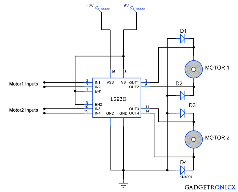
- L293D Motor driver – To drive the motor from Arduino using Arduino signals
- Power Supply – Supply to our entire project
- Regulator (L7805CV) – Regulating the input voltage to project
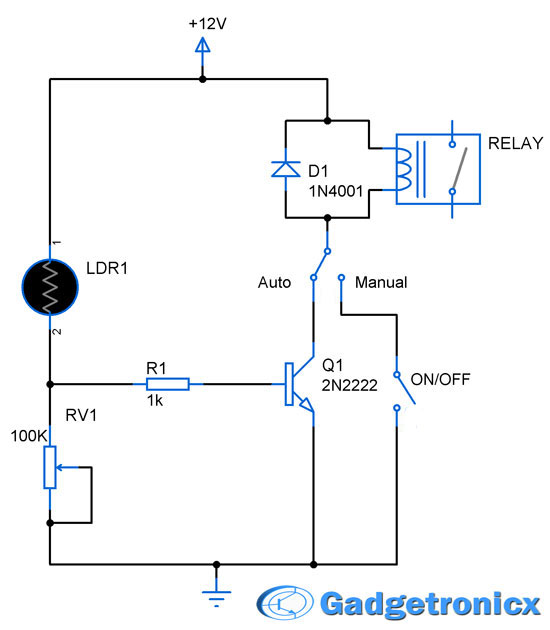
- LDR – Detect the condition of drive (Day or night)
- Button – Turn ON/OFF vehicle
OUTPUT PERIFERALS:
- Ultrasonic Sensor – To detect the obstacles in the road
- Buzzer – Sounding element
- DC motor – Drive for the vehicle
- LED – Indicator
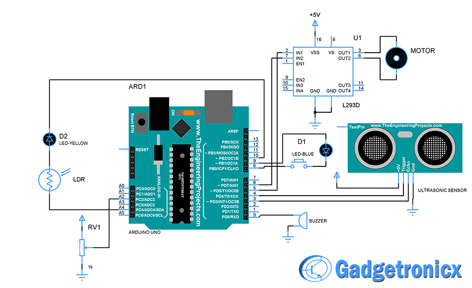
SCHEMATIC DIAGRAM OF SMART VEHICLE:
WORKING EXPLANATION:
The smart vehicle will only start actor pressing the button, also on/off condition of the vehicle is indicated by blue LED. Once the button is pressed DC motor and ultrasonic sensor will get activated. Hence the vehicle starts moving based on that decide speed provided by the controller.
Also the LDR is used to detect the condition that is day or night. Also in this vehicle user can easily gain control of the drive. When can anyone roadies detected by the ultrasonic sensor controller alert the user. This will help user to avoid potential accidents.
When your vehicle stuck in a traffic it will continuously burn fuel. Somehow this should be avoided and here in a project controller wait for for a timer for 10 seconds if it did detect nil motion it will turn off the Vehicle. Again you can turn the engine on by pressing the button.
Take care while setting the value of photoresistor. TO do this you should measure the sensor value during day and night and then set out the optimum value which suits your project.
CODE:
#define trig 4
#define echo 3
const int buttonPin = 8;
int buttonState=0;
int c=0,s,n;
int duration,distance;  //declaration of the  variables
int photocellPin = A4;     // the cell and 10K pulldown are connected to a4
int photocellReading;     // the analog reading from the sensor divider
int LEDpin = 10;          // connect  LED to pin 10 (PWM pin)


void setup()
  {

    Serial.begin(9600);
    pinMode(trig,OUTPUT);
    pinMode(0,OUTPUT);
    pinMode(echo,INPUT);
    pinMode(8, INPUT);
    pinMode(6,OUTPUT);
    pinMode(5,OUTPUT);
    pinMode(A2,INPUT);
    pinMode(9,OUTPUT);

  }

  void loop()
{
  buttonState = digitalRead(buttonPin);
  if (buttonState==HIGH)
      {
            c=1;


      }
  stop:
  if(c==1)
    {
            digitalWrite(9,LOW);
            int val = analogRead(A2);
            val = map(val, 0, 1023, 0, 255);
            photocellReading=analogRead(A4);
            if(photocellReading>580)
            {
              digitalWrite(10,HIGH);
            }
            else
            {
              digitalWrite(10,LOW);

            }
            for(s=0;val==0;s++)
            {
               int val = analogRead(A2);
               val = map(val, 0, 1023, 0, 255);
             //  Serial.println(val);
               if(val!=0)
               {
                break;
               }
                delay(1000);
               if(s==10)
               {
                  c=0;
                  goto stop;
               }
           }
           analogWrite(6,val);
           digitalWrite(5,LOW);
           ultra();
           if(distance<40||distance>150)
           {
                    digitalWrite(0, HIGH);   // turn the buzzer on (HIGH is the voltage level)
                    delay(1000);              // wait for a second
                    digitalWrite(0, LOW);    // turn the buzzer off by making the voltage LOW
                    delay(1000);
                    for(n=val;n>180;)
                        {
                            n=n-20;
                            //Serial.println(n);
                            analogWrite(6,n);
                            delay(1000);
                            digitalWrite(5,LOW);
                            ultra();
                        }
                     if(n>160)
                        {
                                  analogWrite(6,170);
                                  delay(2000);
                        }


             }
              else
             {
                      ultra();
             }
    }
    else
    {
      digitalWrite(9,HIGH);
    }
  }
  void ultra()
{
                    digitalWrite(trig,LOW);        //set the trig pin to low
                    delayMicroseconds(2000);       //pause to let signal settle
                    digitalWrite(trig,HIGH);       //set the trig pin to high
                    delayMicroseconds(10);        //pause signal at high state
                    digitalWrite(trig,LOW);         //set the trig pin to low
                    duration = pulseIn(echo,HIGH); //measure time at echo pin in microseconds
                    distance = duration/58;     //converting the time in distance(centimeters)
                     Serial.println(distance);
}
WORKING VIDEO:
MAKERS:
- Gopal Rathi
- Kodipyaka Sindhu
- Macharla Kavya Sri

