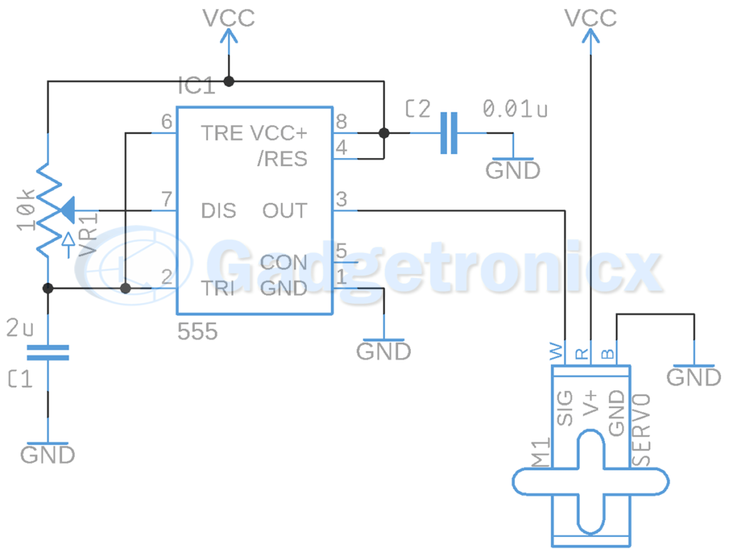
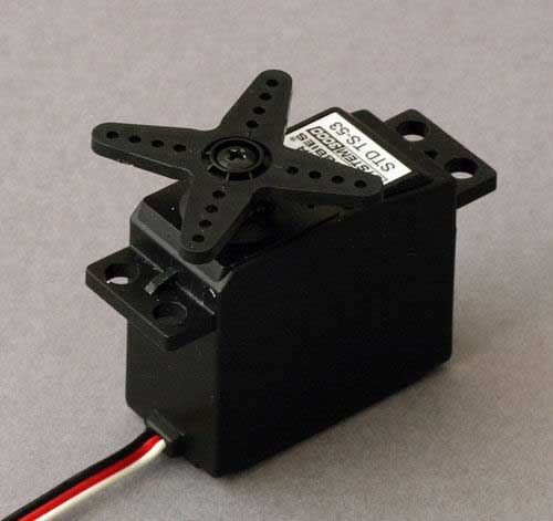
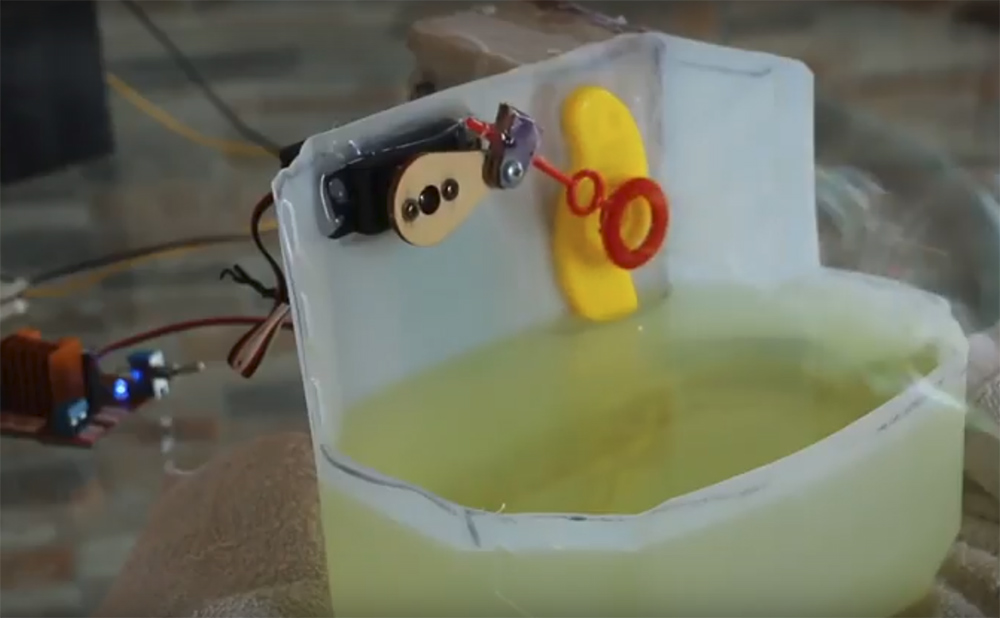
Servo motors are employed in variety of applications like Robotics, Industries, Computers, Doors, Toys and much more. But unlike generic DC motor we can control the angle of Servo motor. This gives more precise movements using this motor. But Servos require special circuitry for it to operate. This is where the above Servo motor driver circuit comes into play and this circuit uses IC 555 to perform this job. Read through this tutorial for better understanding of Servo motor and its working.
PARTS USED:
- Battery 6V
- Timer 555
- Potentiometer 10kOhm – 1
- Capacitor 2uF – 1
- Capacitor 0.01uF – 1
WORKING OF SERVO MOTOR DRIVER CIRCUIT:
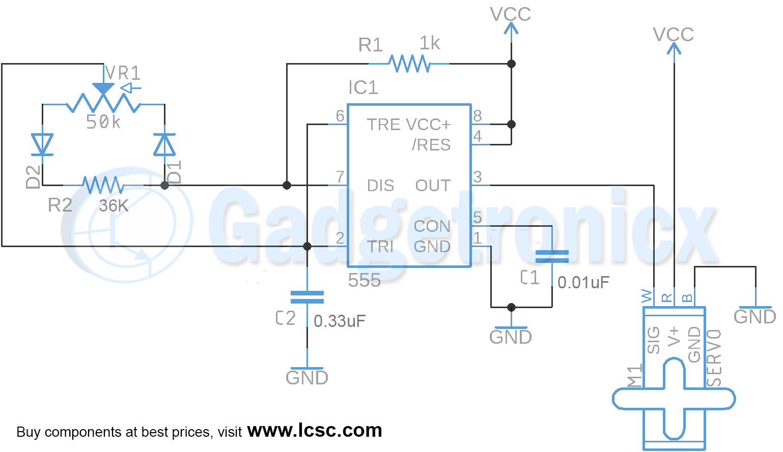
Servo motor is nothing more than a DC motor that can be adjusted its position with a control signal. Here we need to connect the GND and Voltage supply to the motor and build an electronic circuit to feed the control signal to it. This allows us to control the motor. For this the Servo motor uses PWM signal to adjust its position so we use a 555 timer which is configured as Astable Multivibrator. Here in this Astable configuration we use Potentiometer to generate a PWM signal of 20ms time period.
We are choosing the Potentiometer to be 10k Ohms. If we set the Potentiometer to 10kOhm max, it means that we are going to need a 2uF Capacitor, so we now can adjust the duty cycle of the PWM. This control the position of the servo motor because Servo reads the duty cycle of a PWM signal of approximately 20ms to adjust its position. The time period of ON time of PWM signal decides the angle which the Servo will rotate. So the change in Potentiometer value will alter the ON time period of output signal and this alters the angle of rotation ( 45 or 90 or 180 ).
NOTE:
- Time period of the output signal needs to be on point for Servo rotation.
- Calibration of POT to achieve approximate ON time might take some time.

