 |
| Infra Red Jammer Circuit |
Remote jammer circuit can be used to play pranks with your friends and its basically a fun ciruit to try on. And this circuit is very very easy to build and it will take only ten minutes. Also its operation is easy to understand so lets see that hoe this circuit works as a effective remote jammer.
WORKING OF CIRCUIT:
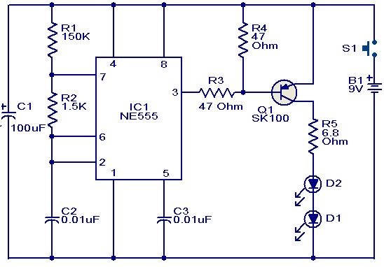
Most of the TV remotes have 38KHz as operating frequency.And a flood of IR beams in the same frequency can easily confuse the TV receiver so that the remote gets jammed.The circuit is nothing but an Astable Multivibrator based on NE555 IC.The output of NE555 is used to drive the IR LEDs. Not only the TV remotes, but any IR remotes operating in the 38KHz frequency region can also be jammed using this circuit.
Here 5V battery can be used to power the circuit.The frequency of the above circuit is decided by three major components. They are R1, R3 and C2 which is attached to IC555 in the above circuit. Lets do some math to see how i have fixed these component values for desired output frequency.
Freq= 1.45 / (R3 +2R1) C2
= 1.45 / (470 + 2*1690)*100*10
= 37.6 Khz
This fixes the frequency of the above circuit and now you are ready to annoy people, Have fun.You can substitute a POT instead of resistor R1 for altering the output frequency produced


sir, can i also build mobile network jammer circuit with the use of same circuit.??
Faheem,
No you can’t this uses Infra Red whereas mobile phone frequency band is in the range of microwave frequencies
Ive had a quick look at the infra-red Remote jammer circuit and can only find 3 resistors and no Pot R4. Can you please indicate where such a component would be located in the circuit, the current circuit shows a 5V supply rail but the notes re Pot R4 suppoort the use of a 9V battery.
Hi Brent,
Apologies for the error. Thanks for pointing this out. This article was written quite a long time ago, updated with right info now.