Device activators are the circuits which is capable of switching high power appliances using simple components. Generally device activator circuits uses simple push buttons and switches as an activating element to trigger the operation of device. However in this device activator a simple household remote is gonna act as activating element. This makes this activator to operate without a wired medium.
WORKING OF DEVICE ACTIVATOR CIRCUIT:
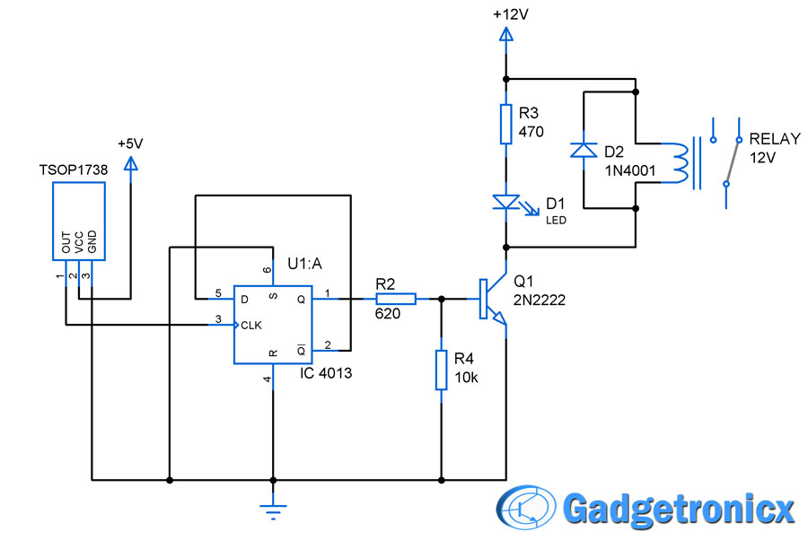
This circuit uses a IR sensor TSOP1738 which is capable of sensing IR signals of frequency 38Khz at which the most household gadget remote operates. So any household remote can be used to activate this above circuit. The TSOP1738 is a active low device which gives logic 0 as output when IR signals incident on it and logic 1 when no in absence of signal.
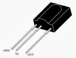
TSOP1738 pin diagram
An edge triggered RS Flip Flop IC CD4013 used to activate the device. It was wired in such a way that it changes its output state when there is a change in input clock levels. The output from the IR sensor was fed into Clock pin of this IC. Therefore whenever IR signal from any remote falls on to TSOP1738 the Flip Flop changes its output state making the device ON/OFF accordingly.
Transistor Q1 2N2222 acts as a switch since the flip flop cannot source high current to drive the relay. R2 is used to limit the base current and R4 acts as pull down resistor to ensure the transistor state. LED D1 was used as an functionality indicator and R3 to limit the LED current. Relay was used to turn ON/OFF the device connected to it, you can use any device with it provided relay and transistor withstands the current rating of the device. And D2 acts as a protection diode to prevent reverse flow of current.
NOTE:
- You can activate any device using this circuit but make sure that the transistor and relay can handle the device current without getting damaged.

RE: “And D1 acts as a protection diode”
Should that be D2?
David,
Corrected now, thanks.