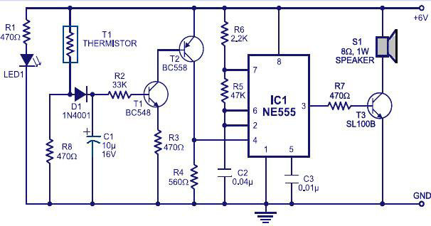
Alarm Circuits are used everywhere to alert the nearby in case of any special events and act accordingly. Rain alarm circuit is something that will be used to indicate the one nearby in case of rain. These kind of alarms can be used in irrigation, water conservation techniques and much more. This Rain alarm circuit is built around well known IC 555 with few transistors and a speaker.
WORKING OF RAIN ALARM CIRCUIT:
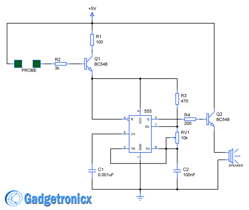
The working begins with the detection of rain which was done by means of a simple probe which was connected in such a way to establish connection between the Power supply Vcc to the base of transistor Q1. Probe might be two piece of wires which placed closer to each other. Since water being a good conductor of electricity it bridges the gap between these wires and conducts current to the base of the transistor Q1 during rain. This provides the supply voltage to IC 555 which forms the sounding part of this circuit.
IC 555 was wired in astable mode where the chip will emit continuous square pulses. These square pulses are then fed into a speaker for producing the alarm sound. Initially when there is no rain the IC 555 will be in deactivated state since there will be no supply to the chip. But when rain activates the Transistor Q1 which in turn activates the 555 and therefore the speaker connected to it starts producing the alarm alert.
NOTE:
- You can use 3Watt 8 Ohm speaker to produce the alarm sound.
- The pot RV1 can be adjusted to alter the alerting sound frequency.

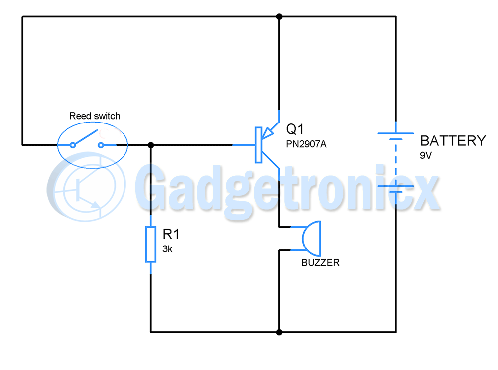
Have you tried this water level sensor? NPN transistors are off unless the base is pulled up in voltage. PNP transistors would be more sensitive to the wires touching the water because they turn on when the base is pulled down.
Marcel,
Couldn’t get you clearly. I believe the NPN transistor is good enough to do the job since the base potential of the Q1 remains low (i.e in off state) unless the probe comes in contact with the water.