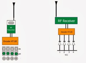
The Radio Frequency RF remote control circuit has wide range of applications and we have been using this in our daily life. And its important for Electronics engineers and hobbyist to understand the operation of RF based wireless remote control to achieve long distant communication. This article brings you brief explanation of RF transmitter and receiver circuits through which you can achieve the long distant communication and also can be used as a RF based wireless remote control.
RADIO FREQUENCY (RF) TRANSMITTER:
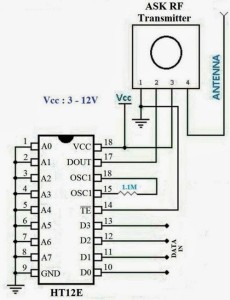
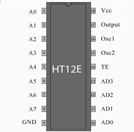
The transmitter part of the our wireless remote control comprises of two components a Encoder HT12E and a ASK RF transmitter module which is used for data transmission. The IC HT12E was a Encoder IC which is capable of converting 12 bit parallel data inputs into serial outputs. These 12 bits are classified into 8 address bits(A0-A7) and 4 data bits (D0-D3). The address bits are used to provide secured wireless transmission between the transmitter and the receiver. The address bits used in the transmitter should be similar to the bits used in the receiver part for enabling communication between the Tx and Rx modules. To understand the working of this circuit better i strongly recommend you to go through this article Working of HT12E encoder.
In the above circuit as you can see that the pins D0 to D3 are assigned for the feeding the data into the encoder. The pins can be connected to switches enabling the logic 1 or logic 0 to the Encoder IC. The address pins was grounded and if you want your communication to be secured , vary the address bit values in the encoder and remember to use the same address value in the decoder.
The input data bits are encoded by the IC and it was obtained through DOUT pin of the IC and it can be directly fed into the transmitter module. These transmitter uses ASK signalling scheme for wireless transmission of bits. The Tx module is of various types and you can choose the one which suits your requirements such as distance of transmission and power consumption.
RADIO FREQUENCY RADIO RECEIVER:
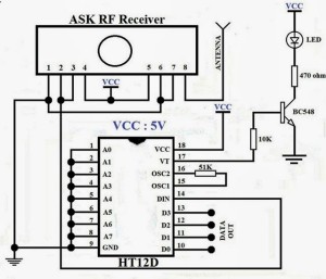
The Receiver is comprised of HT12D a matching decoder IC and a ASK RF receiver module for receiving the incoming signal from the transmitter. The HT12D was a matching decoder IC to the HT12E which was consists of similar 8 bit Address bits (A0-A7) and 4 data output pins (D0-D3) to obtain the input data sent through the HT12E IC. For detailed description of this decoder IC check out this article Working of HT12D decoder.
The address bits A0-A7 was connected to ground since the all the address bits in the encoder also connected to the ground. The HT12D IC has a special pin known as VT which gives out high signal when the connection between the transmitter and receiver was established. The Decoder IC checks the address values of the incoming signal and then sends out the high signal to the VT pin, a LED was connected to it for indication of signal connection establishment.
RF TRANSMITTER AND RECEIVER MODULES:
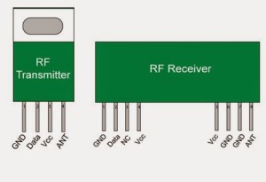
Here is the pin diagram of RF transmitter and receiver modules used in the circuit diagram.
The Antenna size also holds a significant position in a RF based wireless communication link. The suggested Antenna length is 17cm for modules of operating frequency around 433 Mhz. Now your circuit is ready and you can now use it either as Remote control or send simple data through wireless medium.




Hi frank Donald.
Basically I am from electrical engineer. I need your help to build remote for operating home lights. Can u provide Relay latching circuit for outputs.
Hi…I’m trying to make rf remote switch to control three appliances with these encoder and decoder. So please guide me.
How can I program it to control a brushless motor?
Mohamed,
The HT encoder and decoder IC’s cannot be programmed
does it work without the antenna (but shorter range)?
if it needs the antenna… how to make a good one?
Meena Bassem,
No it doesn’t work without an antenna. Kindly do understand that the Encoder is used to encode the data bits (i.e to format the data you are about to transmit) this doesn’t have anything to do with the transmission part. The encoded data bits needed to follow a modulation or signalling scheme in order to make a efficient transmission so that ASK tx and rx module was used. I would advice you to buy one rather than try making one. Hope this answer helps you.
actually, i believe my problem is not just the antenna. i’m not sure that my HT12E is working fine. for the D0~3 pins, if they are active low. doesn’t it mean that i should get a VCC on them (or at least an active high)? i used a voltmeter and i only get something around 0.5~1.5V and i’m pretty sure that’s not logic high.is it normal or there’s something wrong with the IC?
Meena Bassem,
I think you got confused over the terms. D0-D3 pins are meant for feeding the input to the Encoder IC that is logic 0 and logic 1. That is you can connect a switch which is connected to the high level supply at the other end. When the switch is pressed it feeds high input to the pins and when it open it will feed low state. I don’t get the point in using voltmeter to measure the o/p voltage. If you have any doubts in the input parameters of IC do check the HT12E datasheet. It might lighten you up, hope it helps.
Ok, i checked the datasheet again.the Data pins are CMOS IN PUll-High.to use them connect them to the ground, or just leave them.
and they are active low. when a switch is pressed, they are pulled low (logic 0). so doesn’t it mean that they should be high when the button is not pressed? i mean if the button is not pressed and there’s already a 0.5~1.5V on the pin (logic low) what does pressing the button (0v) do if it’s already in logic low state?. please let me know if i’m getting this wrong
Meena Bassem,
I think i got your question now. Yes the pins are active low and it will be activated that is read as logic 1 when the pin is low or grounded. When the Pin is left open it won’t be in a low state it will be in floating state there is a difference, in floating state the logical level of the pin cannot be determined. However the datasheet assures you that the pin will read the input data as logic 0 when the switch is left open. So i guess it’s good to do it as specified in the datasheet. Also in CMOS technology 1.5V doesn’t represent logic low level, kindly refer this Logic levels of CMOS technology for more understanding. If problem still persists do use a pull up resistor of 10k for all data pins, that may keep the pins high as long as the button is pressed. Hope these suggestions helped you.
First of all. Thanks a lot for your support Frank. it was none of that, the IC was not faulty or anything.it was all about the antenna. here’s what happened.
i connected the Pull-up resistors, grounded the TE pin, when i noticed that the VT (valid transmission) pin at the receiver blinked.i noticed that this happened when i accidentally touched the place for the antenna at the transmitter. a few minutes later after realizing that, connected a short wire to that place and connected the TE pin to a button instead of direct ground. now when i press it, the led at VT is always on. i removed the pull-up resistors and only kept the buttons and it works fine. turned out the antenna is really important.
so, now how do i connect the antenna? i mean. how do i make one that gives really good range?
Meena Bassem,
Happy to see you figure that issue out by yourself, congrats. Actually we are done with the encoding still there is two phases to go Modulation and transmission. You need to build a modulator to modulate the encoded data bits and then transmit them to the receiver end. I suggest to buy TX and RX pair modules, this will make your job easier.
Actually i’ve been using AVR microcontrollers a lot recently.if it’s working fine with the buttons, it should work fine with atmega8 or something. i can take care of the rest without problem. Thanks a lot for your support Frank
Meena Bassem,
AVR controllers are just great to work with and i personally love it. If you have any doubts don’t hesitate to post here. Also i have sent a mail to your id with a requisition , do check it and provide your reply. Have a great day.