Interfacing of LCD plays a significant role in wide range of digital display applications such as Voltmeter, Ammeter, Locker etc. But many times we find it difficult to interface and program the LCD properly to make it display our desired characters. Through this tutorial I intend to explain about programming lcd in both 4 bit and 8 bit mode with 8051 Microcontroller and programming it using Embedded C.
16×2 LCD:
This type of LCD module is very common and used widely in many types of display applications. It consists of 16 rows and 2 columns of 5×7 dot matrices. The LCD display was a 16 pin package with back light, contrast adjustment and 5×7 dot resolution. It consists of two built in registers known as Data and Command register each has a specific function to perform. The Data register is for writing the data to be displayed and Command register is to write the commands. The pin description of 16×2 LCD was given below.
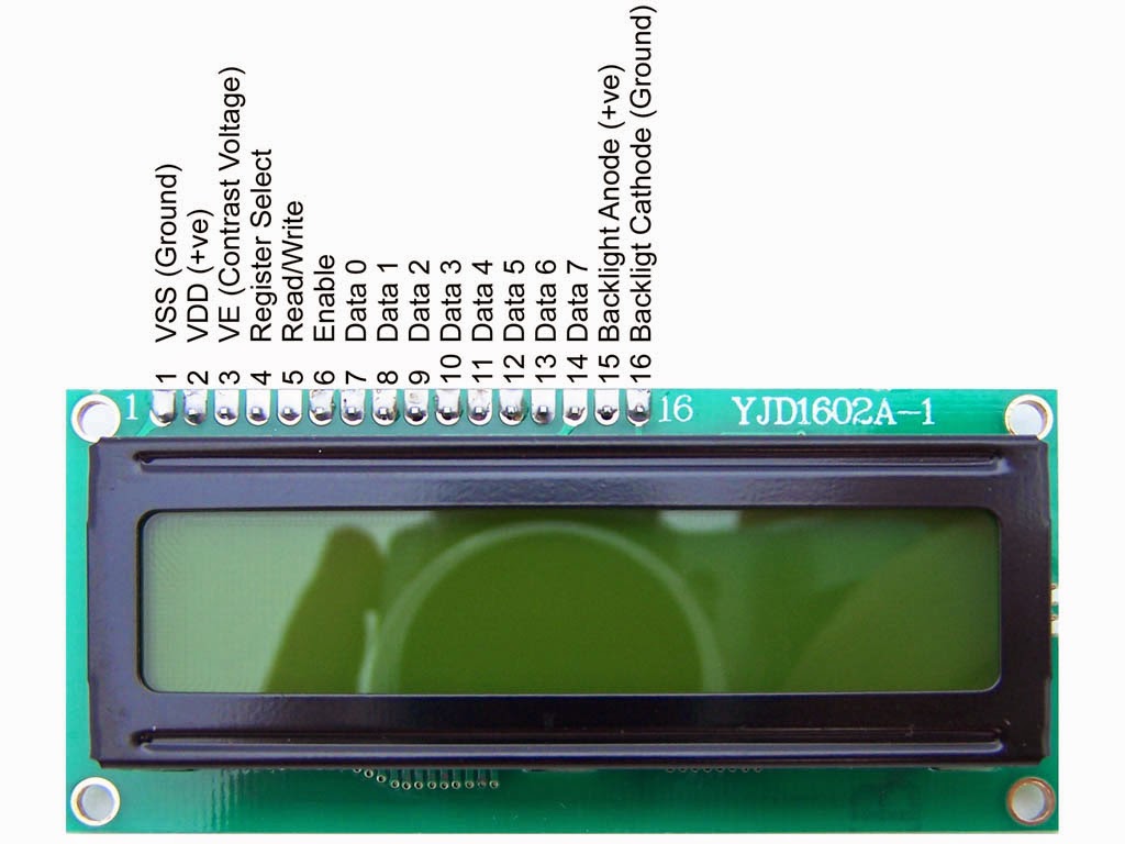 The Data and the Command both are fed to the LCD through the data pins D0 to D7 but the logic state in the RS pin decides whether it is data or command given to LCD. For sending commands the RS pin should be Logic 0 and for the data the RS Pin should be in Logic 1 or high state. After holding logic 0 or logic 1 at RS pin the microcontroller should wait for specific time for LCD to process it before sending the next command or data.
COMMANDS FOR THE LCD:
The commands to the LCD was given in order to initialize the LCD and to give the starting address or position of the characters to be written in the LCD. The various commands to the LCD is given below.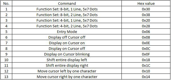 The above commands perform the function specified to them and should be given to the LCD with the Register select (RS) pin in logic 0.
MODE OF OPERATION:
- 8 Bit mode.
- 4 Bit mode.
8 BIT MODE:
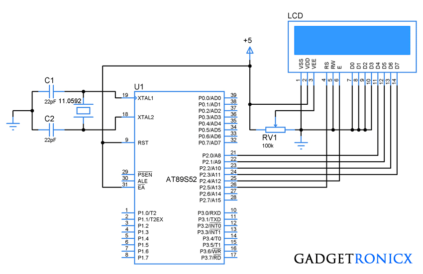
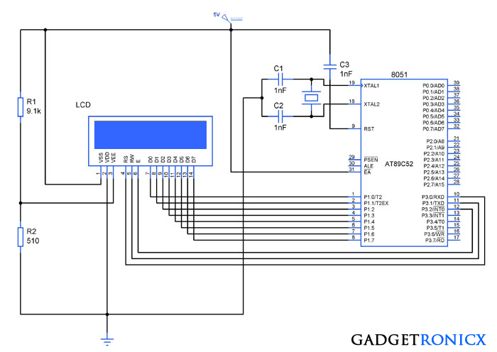
In 8 bit mode LCD requires uses 8 pins for data/command transmission from the microcontroller. The data bytes will be sent through the pins (D0-D7) along with EN,RS and RW(optional) of the LCD. So we need to dedicate a total of 11 pins from the Microcontroller to the LCD.
CONNECTION DIAGRM:
INITIALIZING THE LCD:
The first step is initializing the LCD connected by giving the command input through data line D0-D7. For initializing the LCD following commands should be given to the LCD module
- RS pin should be low to tell the LCD that the incoming byte is a command, so make it low.
- Place the byte in D0-D7 pins of LCD and set the EN pin to high and then make it low with time delay of 10ms between them.
- Send 38H command to use 2 lines 5×7 matrix in 8 bit mode.
- Send 0FH for making the LCD, cursor and Cursor blinking ON.
- Send 06H for incrementing cursor position.
- Finally 01H and 02H for clearing screen and returning home.
DATA/COMMAND TRANSMISSION TO THE LCD:
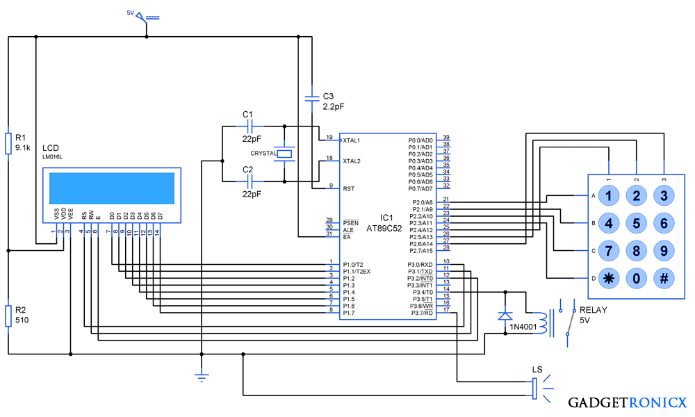
The data transmission to a LCD must be performed by means of assigning logic states to three pins RS and E. R/W pin is not needed so we can ground it as shown in the schematic diagram. The data is send to the module by following these steps.
- RS pin should be high for a data transmission and low for a command transmission.
- Place the data/command in the data lines D0-D7 of the LCD.
- Pulse EN pin from high to low with certain time delay for transmission to complete.
Now lets move into the Programming of the LCD using this AT89S52 microcontroller and this programming was done by using Keil Uvision Software.
CODE:
#include<reg51.h>
#define LCD P2
sbit RS=P3^0;
sbit EN=P3^1;
unsigned char txt[12]="GADGETRONICX";       //Data to display
void delay()
 {
   int k;
   for(k=0;k<=1000;k++);
  }
void lcd(char a,short int b)       //Subroutine for command and data transmission
  {
   LCD=a;                             //Placing byte in D0-D7 lines of LCD
   RS=b;                              //0 for command and 1 for data
   EN=1;
   delay();
   EN=0;
  }
void main()
{
   int i=0;
   lcd(0x38,0);                      //Initializing LCD
   lcd(0x0f,0);
   lcd(0x01,0);
   lcd(0x02,0);
   lcd(0x80,0);
   for(i=0;i<=11;i++)           //Transmitting Data
    {
      lcd(txt[i],1);
    }
   while(1);
 }
4 BIT MODE:
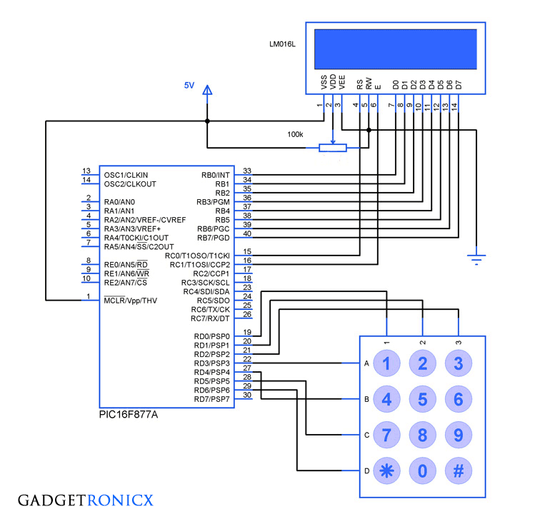
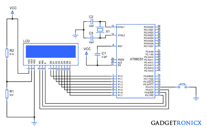
In 8 bit mode LCD requires uses 4 pins for data/command transmission from the microcontroller. The data/ command bytes will be sent through the pins (D4-D7) higher bits along with EN,RS and RW(optional) of the LCD. So we need to dedicate a total of 7 pins from the Microcontroller to the LCD.
The main difference between the 4 and 8 bit mode is usage of pins from the microcontroller. Also 8 bit mode is faster than the four bit mode which sends the data in the form of nibbles (4 bits).
DESIGN:
INITIALIZING THE LCD:
The first step in coding the LCD is initializing the LCD connected by giving the commands as input through the data line D4-D7 in the form of Nibbles. For initializing the LCD following a specific reset sequence should be given and then initialized to follow the 4 bit mode.
- Place the byte in D4-D7 pins of LCD and set the EN pin to high and then make it low with time delay of 10ms between them.
- Send 28H command to use 2 lines 5×7 matrix in 4 bit mode.
- This should be sent in form of nibbles we will send 2H first and 8H next.
- Send 0FH for making the LCD, cursor and Cursor blinking ON.
- Send 06H for incrementing cursor position.
- Finally 01 and 02 for clearing screen and returning home.
DATA/COMMAND TRANSMISSION TO THE LCD:
The data transmission to a LCD must be performed by means of assigning logic states to three pins RS and E. R/W pin is not needed so we can ground it as shown in the schematic diagram. The data is send to the module by following these steps.
- RS pin should be high to convey LCD a data transmission is going to take place.
- Place the Upper nibble in the lower four bits of Port 2 by means of bit shifting and mask the upper four bits.
- Pulse EN pin from high to low with certain time delay for transmission to complete.
- Now place the lower nibble and mask the rest of the bits, then repeat step 3.
CODE:
#include<reg51.h>
#define LCD     P2
#define ENABLE      0x10
#define REG_SL      0x20

void delay()
 {
   int i,j;
   for(i=0;i<=500;i++);
   for(j=0;j<=500;j++);
 }

void lcd_reset()                   //Reset sequence as stated in the LCD datasheet
 {
LCD = 0xFF;
delay();
LCD = 0x03|ENABLE;
LCD = 0x03;
delay();
LCD = 0x03|ENABLE;
LCD = 0x03;
delay();
LCD = 0x03|ENABLE;
LCD = 0x03;
delay();
LCD = 0x02|ENABLE;
LCD = 0x02;
delay();
 }

void lcd_cmd(char cmd)               //Subroutine to send command
 {
LCD = ((cmd>>4)&0x0F)|ENABLE;     //Sending higher nibble by shifting with Pulsing Enable high
delay();
LCD = ((cmd>>4)&0x0F);
  delay();
LCD = (cmd & 0x0F)|ENABLE;          //Sending lower nibble Enable low
LCD = (cmd & 0x0F);
 }

void lcd_data (char *dat)          //Subroutine to send data
 {
  while(*dat!='')
{
LCD = (((*dat>>4)&0x0F)|ENABLE|REG_SL); //Sending data by making RS=1
delay();
LCD = (((*dat>>4)&0x0F)|REG_SL);
delay();
LCD = ((*dat & 0x0F)|ENABLE|REG_SL);
delay();
LCD = ((*dat & 0x0F)|REG_SL);
delay();
dat++;
}
 }

void lcd_init ()
 {
lcd_cmd(0x28);       // 4-bit mode - 2 line - 5x7 font.
lcd_cmd(0x0F);       // Display cursor with blink.
lcd_cmd(0x06);       // Automatic Increment - No Display shift.
   lcd_cmd(0x01);
   lcd_cmd(0x02);       //Clear screen and return home
lcd_cmd(0x80);       // First row first column
  }

 void main()
  {
    lcd_reset();
    lcd_init();
    lcd_data("GADGETRONICX");
    while(1);
  }
NOTE:
- Sometimes you might also want to use reset sequence for 8 bit mode to make the LCD work properly, in that case transmit the command “0x30” with enable pulse from high to low three times with certain delay in between each command.
- Time delay for processing command/data may vary depending on the LCD , so in case you face any problem with command/data transmission try increasing the delay between high to low enable transition.


mobile lcd point tips
how can i modify automatic watering system by using LDR,humidity sensor and push button together.please!
Kindly post this comment in the corresponding article page. It will easier for me to answer and others who will be looking for answers.
well explained but i feel the diagram is not very clear have to magnify the design bit straining
Will post a clear design.
sir how to design timers in evencounter mode
Tulasi,
Even counter? please brief your question