In Embedded systems, communication protocols holds a special place as it opens up ways to efficiently exchange data between devices. There are lot of protocols exists in embedded world but out of all we will come across few protocols more often than the others. We conducted a poll across Embedded engineers/ enthusiast communities across internet and compiled a list of seven communication protocols that are so popular and worth to be aware of.
1. SPI(Serial Peripheral Interface) Protocol:
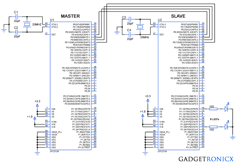
The SPI is a full duplex protocol which uses master slave configuration to establish communication. Motorola invented this protocol in 1980. SPI is used in microcontrollers with interfaces like EEPROM, LCD displays, etc.
SPI protocol comprises of four pins:
- SCLK: Serial Clock ( Clock source for data transmission )
- MOSI: Master Output Slave Input (Output data from Master)
- MISO: Master Input Slave Output (Output data from Slave)
- SS: Slave Select ( Slave selection from multiple slaves by Master)
Additional SS pins are necessary when master device needs to control more than one slaves. One master can control multiple slaves. SPI protocol supports high speed data transfer with bus speed typically stand around 50Mhz therefore the data transmission speed can be go up to 50Mbps.
Data Transmission:
The master device has to select the slave to which the data needs to be sent using the Slave Select pin by activating a low input signal. Then the clock pulse from SCLK pin will be sent to slave to synchronize the transmission. The data from Master pin goes through MOSI pin and from slave to master comes through MISO pin.
2. I2C(Inter-Integrated Circuit) Protocol:
I2C is a two wire serial bus communication protocol invented in 1982 by Philips Semiconductors. It is a two-wire communication interface and commonly used to connect low-speed devices like microcontrollers, A/D and D/A converters, I/O devices and other peripherals in embedded systems.
I2C uses two pins to establish communication:
- SDA: Serial Data Line
- SCL: Serial Clock Line
I2C protocol supports different data speed based on their mode of operation. Data transfer speed 100kbit/s when operating in standard mode and 400 kbit/s when operating in full speed mode.
Data Transmission:
In I2C protocol each device is given a specific address. When a master wishes to transfer data to a slave, it sends the address of slave device through SDA pin for which the message is intended to. It is followed by Data frame and only the slave with the specified address will accept this incoming data.
3. USART(Universal Synchronous/Asynchronous Receiver/Transmitter) Protocol:
USART is a serial communication protocol developed by Digital Equipment Corporation in 1960’s. It supports Full duplex, Half duplex and simplex communication. This is one of the most popular protocol and will be in almost all microcontrollers
The communication in UART takes place through two pins.
- RX: Receive the incoming data
- TX: Transmits the outgoing data
Data transmission in USART takes place by means of data packets which usually consists of 8 data bits, start bits and parity bit to perform error correction.
Data Transmission:
As mentioned above Data in USART will be sent in the form of data packets or data frame. The data frame starts with a start bit, followed by data bits and then by parity and stop bit. Most microcontrollers provide ways to configure the number of data bits and composition of the data frame.
4. CAN(Control Area Network) Protocol:
Controller Area Network or CAN protocol is designed to share data among multiple interfaces to reduce the complexity of connectivity and wiring. This was first developed and used in automobiles to establish communication between different parts of the automobile like engine, bakes, air conditioner etc while reducing the wiring in it. The unique feature about CAN protocol is that a data transmitted from one CAN device or node will be available to all the devices connected in the CAN bus.
This protocol uses two wires for communication with other CAN devices
- CAN HIGH
- CAN LOW
There are two types of CAN protocols: Standard CAN and Extended CAN.
Data Transmission:
In standard CAN any node can transmit data through the bus to any node. CAN data frame starts with a start bit followed by a 11 bit identifier which sets the priority of the message. Message with higher priority gains access to the CAN bus when two devices attempt to send message at the same time. RTR bit indicates if the data is being requested from a particular node. IDE bit marks whether it is a standard or extended CAN frame. Data length code bits follows IDE which indicates the length of data. Then comes the message itself. Cyclic redundancy check and ACK bits follows then and are used to error check to ensure proper transmission of data. A 7 bit end of frame which marks the end of the message.
5. USB(Universal Serial Bus) Protocol:
USB is one of the well developed and most used communication protocol. Despite having different standards and hardware types, it is considered to be versatile and effective in embedded systems. USB communication takes place by means of polling where the host device initiates the data transfer. When a device connects to the host it assigns address to the and uses it to perform data transfer.
USB protocol uses below pins to function
- VCC – For power supply
- GND – To close the circuit
- D+ – Data transfer differential line
- D- – Data receive differential line
Data Transmission:
Every data transfer in a USB communication is done by means of data packets, Generally there are three components in a data packet : a token packet which carries information such as data type, device address. Next the datapacket which holds the actual data to be transferred and EOP to indicate the data packet is ended.
6. ETHERNET Protocol
Ethernet is most popular networking protocol used to establish connections right from LAN to WAN. With the growth in IOT, this protocol has become indispensable in Embedded systems. This communication protocol has undergone series of revisions over the years to enhance its connectivity and speed. Mostly Ethernet controller chips like WZ1500 will be used with regular microcontrollers to enable the Ethernet connectivity. However some high end Microcontrollers like STM32 will have some degree of inbuilt Ethernet protocol support within. Such microcontrollers use MII or RMII protocol to transmit and receive data within network. Read more about Ethernet protocol.
Data Transmission:
Transmission of data in Ethernet protocol takes the form of data frames. This data frame constitutes of senders address, receiver address, actual data and bits for error correction.
7. RS-485 Protocol:
RS-485 is yet another protocol popular for connecting microcontrollers with external peripherals. This protocol comes in very handy when the data need to be transmitted for over hundreds of meters. Similar to Ethernet protocol most microcontrollers uses external chips like MAX485 to use this protocol. Using this protocol several devices can use the same interface and perform data exchange. More about RS-485 protocol here. These are the pins involved in RS-485 protocol.
- TX+
- TX-
- RX+
- RX-
Data Transmission:
A typical data frame of RS-485 comprises of start bits, receiver address, data bits and stop bits to indicate the end of transmission.
Hope this was informative to you. We will publish part II of this popular communication protocols series soon. If you have any feedback, comments or suggestions do use the comment box below.

