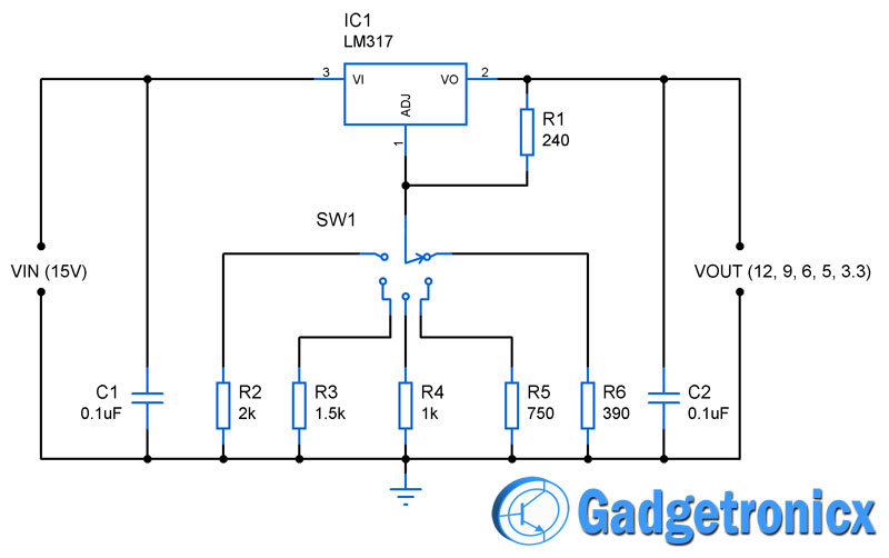
Power Supply circuits can be extremely useful when you are working on a project which requires multiple range of input voltages. Building a dedicated power supply units for each of those can be painful and tedious process. Instead you can build this multiple voltage power supply circuit which provides output in the range of 12 , 9, 6, 5 and 3.3 Volts.
LM317:
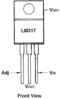
LM317 is a voltage regulator chip which is capable of producing output voltage from 1.2v to 37V with 1.5A of current to the load. The output can be altered by using the Adj pin of the IC. The IC was built in such a way it develops a nominal voltage of 1.25v from the Output pin to the Adj pin. So putting resistor across these two terminals and applying a varied voltage to adj pin will give varied output voltage in Vout pin.
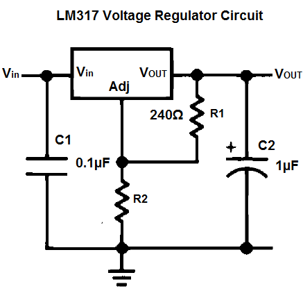
The above schematic shows the simple voltage regulator set up using LM317. Here a potential divider was used to feed the adjusting voltage to the adj pin. The output voltage obtained is given by the formula.
Vout = 1.25V ( 1 + R2 / R1 )
Where R2 and R1 denotes the lower and upper leg of the potential divider used to feed the Adj pin.
WORKING OF MULTIPLE VOLTAGE POWER SUPPLY:
Generally when dealing with electronic circuit five voltage ranges are very commonly used 12, 9, 6, 5 and 3.3V .So we are going to build a single power supply circuit which gives all these output voltages and can be changed using a simple rotary switch SW1.
According to the Vout formula for LM317 varying the resistance in voltage divider will alter the output voltage. So we are going to keep the Resistor R1 fixed and alter the lower leg of the divider with different resistors R2, R3, R4, R5 and R6 which gives out voltages 12, 9, 6, 5 and 3.3.
To calculate the resistance value (lower leg) for our required output voltages we have to rearrange the basic LM317 formula
Vout = 1.25V ( 1 + R2/R1) Rearranging this formula we get
R2 = ( Vout x R1 / 1.25 ) – R1
This formula gives the resistance value (lower leg) for required voltage. To obtain 12V in the output the R2 will be
R2 = ( 12 x 240 / 1.25 ) – 240
R2 = 2064 ohms
Approximating this value will give 2K resistance and therefore we have fixed R2 as 2K in our schematic diagram.
So using the same formula for 9, 6, 5 and 3.3v we will get resistances 1.5K , 1K , 750 and 390 ohms approximately. This forms the resistances R3, R4, R5 and R6 respectively. So summing the above things selecting R2, R3, R4, R5 and R6 using the rotary switch will give 12,9 , 6, 5 and 3.3V in the Vout pin of LM317.
NOTE:
- Using the given formula you can substitute the above resistance values and get the output of your desire in the output pin Vout.
- Capacitor C1 and C2 is used for ripple rejection in the output and input signals of LM317.

Auto power cut off circuit when battery fully charged
Is this circuit available
Just a suggestion. Make sure the rotary switch connects the next terminal, before it disconnects from the first one. “Make before break” Otherwise, for a split second, the switch will be open circuit while you change the voltage. Spiking the output to the maximum. Destroyed a 6v audio IC switching (slowly) between 5v & 6v. These switches can be ordered through your favourite online main stream vendors. Element14, RS, Digikey, etc.
Can you tell me the part number of this switch
Pradeep,
You can use any single pole 5 throw switch for the switch.
The same computation could be done by varying R1 instead. In that case, the open circuit makes the LM317 put the output to the minimum, and then any rotary switch would work.
With R2=3.9kΩ I got these values for the R1 resistances: 2.2kΩ / 1.2kΩ / 560Ω / 390Ω / 330Ω / 180Ω
for the 3,3V / 5V / 9V / 12V / 15V / 24V ranges. The current through the resistors varies from 0.5mA to 5.8mA (in the original, it was constant 5.2mA)
Is there a disadvantage of doing it this way ?
HELLOW can you please tell the multi voltage power supply circuit
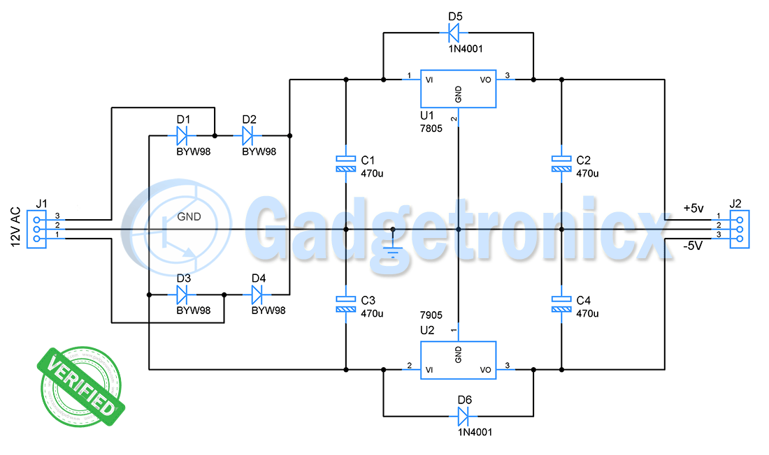
circuit for negative voltages (-5 -9 -12 ) ..????
USE 7905/7909/7912 FOR NEGATIVE O/P
if my load is more than one ampere then what i need to do?
Haris,
You need to look for another regulator.
Haris,
You need to look for another regulator.
Whar does the adj pin mean for?
Hi Arvind,
Adj pin decides the output voltage you get from this IC. It can be calculated by the formula
Vout = 1.25V ( 1 + R2 / R1 )