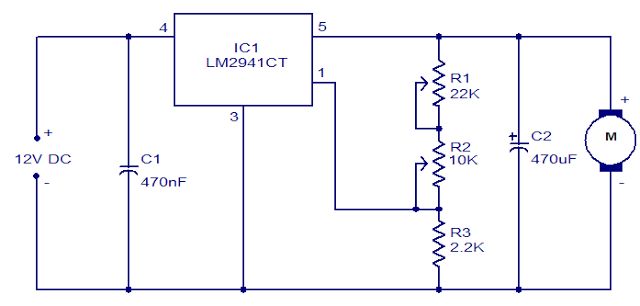
This Motor speed control circuit uses a IC LM2941CT which is a low drop out 1A voltage regulator.This regulator IC posses many cool features like power supply reverse protection, thermal protection, short circuit protection etc.The maximum output current IC can be around 1A.Now lets see the working of this circuit and how it was used to control the motor speed.
WORKING OF MOTOR SPEED CONTROL CIRCUIT:
 |
| LM2941CT |
The above is the pin diagram of LM2941CT.As you can see it consists of 5 pins and each have its assigned specific functions.We are not using the pin 2 in this circuit since we dont need a separate On/Off operation here.The adjusting pin forms the main part of this circuit as it was connected to the potentiometers R1 and R2.
The two potentiometers determines the current flowing through the network.Thus by varying the current flowing through the POT R2 the speed of the motor can be controlled.The POT R1 can be used to control the minimum speed of fan.This circuit is very effective and can control any DC motor of 12v.The working and construction of this circuit is very simple but still effective.




3 phase motor control explain
may i know work on 24v dc supply ? And can i get a circuit for 24volt motor speed control?
Hann,
It won’t work with 24v DC supply.