Motors in electronic circuits serves several purpose in driving things and enables object movement. Its important to drive the motor correctly to achieve the desired output from the circuit. Usually motors are controlled by means of changing polarity of the signals through its terminals to make it run in both directions. And here we are going to employ a H-bridge motor driver IC L298 which is capable of controlling two motors at once. Lets see how this IC L298 works and how to use it in this motor controller circuit.
WORKING OF IC L298:
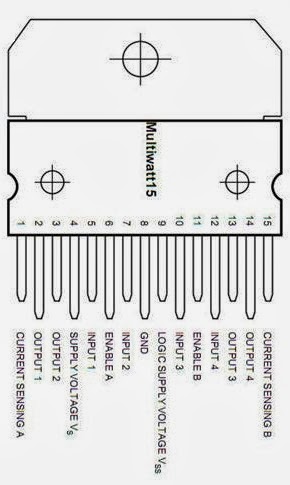
The above given is the pin diagram of the IC L298. There are three input pins for each motor input1 , input 2 and enable 1 controls the motor 1 while input 3,input4 and enable 2 controls the motor 2. The output for motor 1 is obtained from output1/output2 and output3/output4 as. This driver IC uses two different supply voltages that is the voltage given to the pin 9 powers the chip and it should be 5 volts. On the other hand the voltage on pin 4 supplies the motors and it can be upto 46 volts. The IC also comes with two specific pins known as Current sensing A and B which is use to sense the voltage at the resistor connected to it which is proportional to the current related by ohms law. Here in the circuit we didn’t use the current sensing, so we have grounded those pins 1 & 15.
WORKING OF MOTOR CONTROLLER CIRCUIT:
The initial working of the circuit starts with enabling the motors in the output by giving high signal to the enable pins 6 & 11. Here we are going to use both motors so we have connected both the enable pins to the power supply through resistor. The input buttons was added to the input lines for feeding the high signals to the input pins of the L298 IC. So in order to activate a motor 1 you must give high signal to the enable1 pin. Then if you want to drive the motor in forward direction you have to apply high signal to input1 pin and for driving backwards apply high signal to the input2 pin.The below table illustrates the motor action with respect to the given input in the pins input1 &input2.
The same case applies to the motor 2 with control pins enable2, input3 and input4. To make a motor stop slowly apply low signal to the enable lines of the motor. Moreover the L298 does not have built in protection diodes so you have to add those to prevent the IC from getting damaged. This IC also carries a large cooling flange with a hole in it making it easy to attach it with sink.




Hi! Does anybody has a testing diagram for the L298n chip? just to check if it works or not.
Please send me an email.
Thanks!
Mariano
Hi Mariano,
This circuit is tested and it will work. Do try it out and let me know.
hi, are the 10k resistors mandatory on the enables pins ? could we connect directly the 5 volt to the enable ? what kind of diode is used ?
Redouane,
Yes you can connect them directly without the resistors
can use enable pin for pwm speed control
George,
Yes you can.
very usefull
Thanks for your valuable info……
Take care with the L298. It is vulnerable during logic transitions if the input lines change state at the same time. Both halves of the bridge can be on at the same time and short out the supply. This can result in a fairly spectacular self-destruct!
So what is the safe transition state? Both inputs high or both low?
Hi Alvaro,
He mean to say that the change of state for the input lines should not happen at the same time.