 Frequency modulation is one of the primitive yet effective means of wireless communication which is still used in several parts of the world. When comes to building a FM transmitter circuit you have numerous options based on the range of communication. Here is a simple mini FM transmitter circuit that gives a range of about 400 meters.
WORKING OF CIRCUIT:
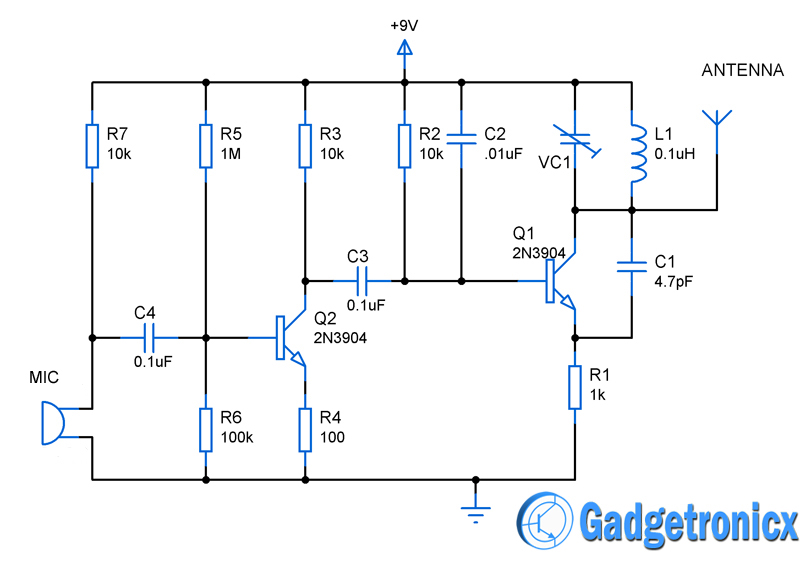
The circuit can be divided in to two parts for better understanding of its working. The first one is the Voice detection part which consists of a simple electret microphone and single stage transistor amplifier to amplify the signals obtained from the microphone. The capacitor C4 was used to block the DC components in the signals whereas Resistor R7 fix the sensitivity of the microphone. The amplifier was built around Transistor Q2 where Resistors R5 and R6 provides the biasing voltage to the base of this transistor Q2.
The next part of the circuit is the modulation part which consists of a tank circuit along with transistor Q1. The LC tank circuit provides the sustained oscillation for the FM modulator. The operating frequency of the tank circuit was given by the equation
f= 1/(2∏√LC)
The VC1 trimmer cap allow us to tune the resonating frequency of our Fm circuit. The capacitor C3 was employed to remove the DC components in the output amplified signal from Q2. C2 was meant for decoupling and R2 to provide the bias voltage. C1 capacitor was added to keep the tank circuit vibrating thereby ensuring the sustained oscillations from the tank circuit. R1 performs the function of current limiting. A simple wire measuring 5 to 8 inches can serve the purpose of antenna in the above circuit.
Refer this Instructable for step by step guide to build this FM transmitter.

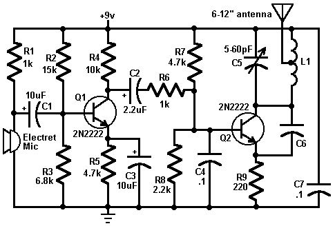





This appears to be an AM transmitter, not FM, as no means is given to actually modulate the frequency of the oscillator. It’s a tank circuit, so one would expect at least a varicap diode, to vary the center frequency.