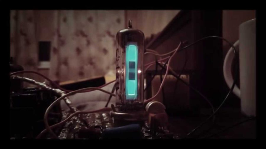
Hi guys, today we are going to be presenting a variation of a vacuum tube and it’s applications. This is the EM80 (or alternatively EM84) magic eye vacuum tube. Historically it found use in early radio receivers, where frequency stability and proper tuning was an issue. Being able to visually show a relatively proper tuning point to the user. Later on, it is used in recording studios to show line level of the recording and helped technicians to adjust accordingly. Nowadays its primary use is a aesthetic addition to vacuum tube amps to show output visually.
The biggest disadvantage is, that it works with high voltages (250V+), thus making it an inappropriate choice for transistor amps, where the voltages in question, rarely exceed 100V. Anyway in today’s tutorial I will show you how to easily bypass this problem with a simple boost converter, specifically designed to be able to power such a tube. The good thing is, that these tubes rarely consume more than a few mA, so a simple boost converter, such as the one showed, makes a good choice for a power supply.
A little about how these tubes operate. Magic eye tubes exploit the principle of Phosphorescence, where a thin layer of phosphorus becomes luminescent, when struck by a ray of electrons at a given intensity. By varying the angle of the ray, the phosphorus screen illuminates at different parts. The same principle is used in Cathode Ray Tubes only difference is magic eye tube has only one dimensional deflection. Whereas the cathode ray tube uses both horizontal and vertical deflection to display an image. This makes the magic eye tube a perfect choice to display a one dimensional V-U characteristic of a given wave in real time.
THE POWER SUPPLY CIRCUIT:

The PSU circuit, basically employs a 555 timer to set a stable oscillation frequency for the MOSFET, which in turn uses the property of inductors, that whenever an abrupt change of current occurs, a voltage spike is induced on the output. That voltage spike gets rectified by the on diode on the output and gets smoothened by the 1uF capacitor. I have intentionally left out the types of the MOSFET and the diode because almost any one would do the job. But do remember to use components with voltage rating higher than 400V.
For instance I used an IRF740 Mosfet and a UF1007 diode, because its a fast diode, but as long as you don’t use a diode from the 1970s, any would do. Use 100uH inductor with rating of at least 2-3A or so, so don’t use a SMD inductor. The 220k/470ohm voltage divider at the output sets the output voltage via employing a negative feedback through the NPN transistor. When output reaches a given voltage the NPN transistor enables and starts dropping the voltage from the CTRL pin of 555 timer. This in turn decreases the duty cycle of the timer, and thus less energy is transferred to the load, keeping the voltage from further increase.
THE MAGIC EYE SETUP:

The circuit is pretty generic, and there are probably a ton of circuits on the internet. I have made only slight variations in the setup. As long as you drive the control grid negatively, and supply the the plate with an appropriate voltage, everything should work properly. A little personal recommendation. The EM80 tube datasheet states, that the plate voltage should be 250V, but I routinely keep it at 300V. Because these kind of tubes quickly suffer from cathode poisoning and you can slightly extend their lifetime by keeping them off rating.
As for the control grid, I stated that you should drive it negatively in respect to ground. There is also the problem with the full deflection. To get full deflection, you should supply -14V to the grid. This leaves you with several options. Either get input directly from output of your amplifier or if that’s still not enough make a simple preamp. The preamp needn’t be very linear, just as long as it reaches the needed voltage at the output. You can make it a relatively high impedance because the circuit has a very high input impedance, and wont load almost any preamp. Anyway the two input diodes rectify the signal, and allow only the negative portion, to reach the grid. The 0.1uF/5Mohm is there to set the attack/release timing for the tube.
You can play around with the value of the capacitor to reach the best signal response which suits your purpose. As for the heater supply, the tube datasheet states the tube works at 6.3V/0.3A. You can use a dropping resistor from 12V supply to get the 6.3V heater voltage. Basically you need to drop 5.7V at 300mA through it. Using ohms law we get a resistor value of 19-20ohm. Use 2W resistor to dissipate the excess heat safely. Using two 33ohm resistors in parallel with a 1W rating, should do the job.

Hi Vladislav,
I am (trying) to repair an old 1960 radio with an EM84 indicator, but as I have no instruments at home probably I will not be able to fully repare it.
The BF amplifier is working well and if I can not get the RF section working I will not be worried, because my idea is using a Bluetooth receiver to send my music to the radio, because here the AM and the FM broadcast are full of commercials and are boring.
I would like to use the current tuning indicator as output level indicator, but I can not see the pictureson your Web. Can you send to me some ideas on how to use the EM84 as sound level indicator?
Thanks in advance
Hi Vladislav, I love the fantastic magic eye kits. I have already built a little turntable pre-amplifier with 2 magic eye tubes. Mine has a little problem, perhaps you can suggest what I might need to do to fix it?
1. The inputs to the magic eye tubes are connected to the output of the pre-amp. This output then goes to the amplifier inputs.
2. When I have the tubes OFF and NOT CONNECTED to the output, the sound is fine
3.. When I have the tubes ON but NOT CONNECTED to the output, the sound is fine
3. When I have the tubes ON and then CONNECTED to the output, it adds a lot of distortion
Can you recommend a circuit schematic or similar that I could use, to somehow stop the tubes distorting the signal?
thanks for your thoughts / advice!
Barney