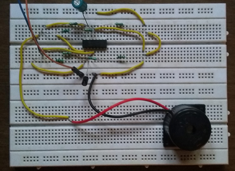
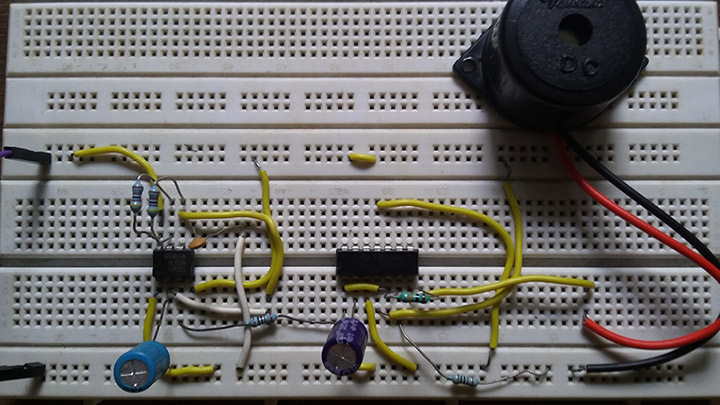
Alarms are pretty handy to use in alerts, detectors, sensors etc. In such applications the loudness of the alarm can be a challenge since some most circuit you find online won’t produce audible sound. So to overcome this defect here is a loud alarm circuit using Opamp IC LM324 and a DC buzzer. You can also hook this up with other circuits to improve the functionalities.
LOUD ALARM CIRCUIT DESIGN:
WORKING OF CIRCUIT:
This circuit consists of two symmetrical blocks which exhibit same working operation. IC U1:A R1..R4 and C1 comprises of a simple comparator set up. Voltage divider formed by R1 and R3 feeds voltage input to the non inverting terminal of the comparator. The resistor R2 and C1 acts as a charging circuit for the above set up.
When the power is switched ON initially due to the voltage divider the voltage at + terminal will be more than than the – terminal of opamp. This makes the output to switch to the positive rail voltage. When voltage in the capacitor exceeds the voltage in the + terminal the output voltage switches to logic 0 low signal.
After switching to logic 0 the cpacitor starts discharging and the voltage drops. This in turn makes the voltage at + terminal to increase and output voltage switches to logic high ‘1’ signal. A positive feedback resistor R4 is meant to the output state stable and prevents false triggering.
The output of first stage is fed into the second stage. The second stage follows the same working principle as the first stage. Therefore the second stage delivers a pulse which varies in its width as output. This pulse is then fed into 3-24v buzzer which produces a siren sound as output.
The capacitor C1 and C2 plays an important role in varying the width of the pulse. Try varying its values to obtain interesting sound variations in the buzzer. You can also use a speaker in place of the buzzer provided enough driving current for it.
WORKING VIDEO:


