I2C (Inter Integrated Circuit) also known as TWI (Two wire Interface) is a bus interface connection that is used in many devices such as Sensors, RTC and EEPROM. Unlike SPI this protocol only uses two wires to establish the connection and hence known as Two wire interface. This protocol will come in handy when the designer needs to conserve the number of pins used to perform the communication. This tutorial will teach you to program I2C protocol in ARM7 Microcontrollers.
I2C PROTOCOL:
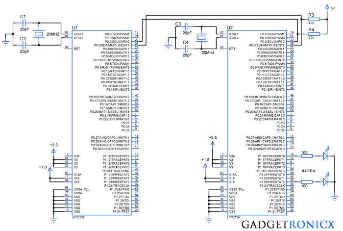
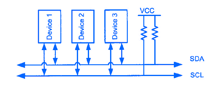
This protocol uses 2 bidirectional open drain pins SDA and SCK for data communication. SCL( Serial Clock) is used to synchronize the data transfer between these two chips and SDA to transfer the data to the devices. Therefore this protocol will allow us to reduce communication pins, package size and power consumption drastically. Each devices connected to the I2C line is known as nodes and the communication lines should be activated by means of a pull up resistor.Each data bit is transferred on the SDA line is synchronized by a high to low pulse clock on the SCL line. And the data line cannot change when the clock line is low.
START AND STOP CONDITIONS:
I2C communications are initiated and terminated by means of a START and STOP Conditions. START condition is generated by a high to low change in SDA line when SCL is high wheras STOP condition is generated by low to high change in SDA line when SCL is low.
SLAVE ADDRESSING:
In I2C each slave device should possess an unique address which will be used by the master to address the slave and transmit the data to it. Usually the communication begins with start condition followed by the slave address of the slave and then comes the data.
I hope i have enough information to get you started with I2C, but i advise you to go through this article I2C bus specification to get a deeper understanding in its working and addressing schemes.
REGISTERS USED:
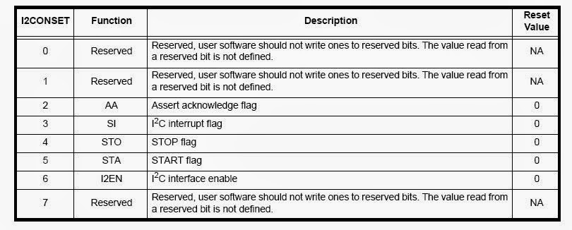
I2CONSET: I2C control register is an 8 bit register which holds the holds the bits to control the I2C communication.
I2STAT: This is an 8 bit read only register which contains the key information and status of the I2C register. The bits in these registers must be checked periodically.
I2DAT: This register holds the data to be transmitted or received. This register can be accessed only when the SI bit is set.
I2ADR: This register holds the slave mode address and used only when the I2C is set to the slave mode.
I2SCLH & I2SCLL: The values in these two registers will be used to set the data rate of the I2C communication. The bit frequency is given the formula
Bit Frequency = Fclk / (I2SCLH+I2SCLL)
I2CONCLR:
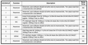
I2C control clear register used to clear the controls of the I2C set using the I2CONSET register.
STEPS TO PROGRAM I2C:
MASTER MODE:
- Load the values in the I2SCLH and I2SCLL register to set the required bit frequency.
- Enable the I2EN bit in the I2CONSET register.
- Set the Acknowledgement bit and start bit in the I2CONSET register.
- Check for the status 0x08 in the I2STAT register which was defined in the datasheet.
- Transmit the slave address, followed by the databytes.
- Send the stop signal by activating the bit STO in the I2CONSET register.
- Disable the I2C by writing 1 to the bit I2EN in the I2CONCLR register,
SLAVE MODE:
- Slave address register should be loaded with the slave address.
- The I2EN bit must be set to enable the I2C function and AA bit must be set to acknowledge general address or call address.
- Receive or transmit data based on the direction bit received along with the slave address.
Kindly refer the datasheet for all modes of program, since the topic is vast and cannot be covered within this article. Also datasheet did an exceptional job in explaining the registers and modes of I2C operation. The link to download the datasheet is available below.
SAMPLE CODE:
#include<lpc21xx.h>
#define AA 2
#define SI 3
#define STO 4
#define STA 5
#define I2EN 6

void wait(unsigned int delay)
{
while(delay--);
}

void i2c_init(void)                         //I2C initilaization
{
I2SCLH=100;                              //Bit frequency calculated value
I2SCLL=100;
I2CONSET=1<<I2EN;
}

int i2c_start()                              //I2C communication start
{
I2CONCLR=1<<3;
I2CONSET=1<<STA;
while(!(I2STAT==0x08));
return 0;
}

int i2c_write(unsigned char buff)      //Data writing through I2C
{
I2CONSET|=1<<SI;
I2DAT=buff;
wait(5000);
I2CONCLR=1<<SI;
wait(5000);
return 0;
}

void i2c_stop(void)                   //Stop the I2C communication
{
 I2CONSET=(1<<STO);
 I2CONCLR=(1<<I2EN);
}

int main(void)
{
VPBDIV=0x02;                   //Setting FCLK frequency
PINSEL0=1<<4|1<<6;       //Selecting I2C communication pins
i2c_init();
i2c_start();
i2c_write(0x00);
i2c_write('A');
i2c_write('B');
i2c_write('C');
i2c_stop();
while(1);
}
NOTE:
- The Bit rate frequency of the I2C must not exceed 400KHZ so make the calculation to follow this criteria.
- Make Changes in the above code as stated in the steps for slave mode to obtain the code for slave controller.
- Pull Up resistors should be used to activate the communication lines.

Hello, I am confused of wait function. How much time is the wait(5000)?
it is 5 seconds. Is not it
Hello, thanks for your examples. How to do i2c read ?
Hi, your project “How to program I2C protocol in ARM Microcontroller” sounds that my mini project can use this circuit. Let me briefly explain my mini project. I intend to build a lighting system which needs a controller to turn on/off LED individually. The controller is able to support 10 rows of extendable modules. Each row will be extended by each light module panel in which each panel support 10 LED lights – maximum 4 such module panels in each row. So, the controller will be able to support 400 lights all together in 10 rows.
Is your project able to support my mini project? How is the addressing done in the extension and how can the controller recognise the extension part automatically? By DIP switch or others? Each light will be controlled by software inddividually to turn on and off. But how can the software recognise the light in the extension panel?
Please help. Thanks.