 |
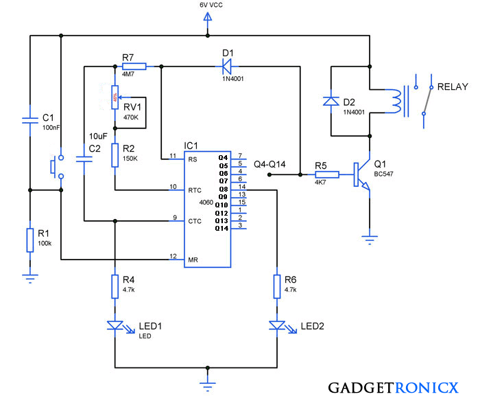
| 24 hour timer Circuit design |
IC 4060:
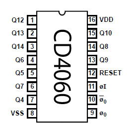 |
| PIn diagram of IC CD4060 |
IC 4060 is a formidable integrated circuit especially used for timing and oscillation purpose. It consists of ten active high outputs that can produce desired time delay from few seconds to hours. IC 4060 is a oscillator binary counter cum frequency divider. This Integrated circuit also has a inbuilt oscillator which is purely based on three inverters. The frequency of the internal oscillator is determined by the value of resistors and capacitors connected with it.
WORKING OF 24 HOURS TIMER CIRCUIT:
This timer works by means of inbuilt oscillator which was wired to produce a signal of specific frequency. When the oscillator is running the counter counts the number of oscillations and it is reflected in the output pins of the Integrated circuit 4060.
RV1 a variable pot was used to alter the frequency of the oscillator, so we can control the speed of count. To be exact by controlling the speed count we can decide the time duration it will take for any given output pin to go high. And from that output pin you can switch your transistor to turn on the relay or activate any device using it.
 |
| Range Table Setup Table |
The above table illustrates the time delay output obtained from each of the pins in the IC 4060. Using this table and performing simple math can help you obtain any time delay of your desire. For example if you want a delay of period 9 hours , the range table shows that it can be obtained from pin 2 of the IC.
The pin 2 need to go high after 9 x 60 x60 = 32400 seconds and setup table tells you to divide this 512. This will give 63 seconds, all you need to do now is to adjust RV1 in such a way the LED1 lights 63 seconds after power is applied. This will give an output at pin 2 after about 9 hours, your desired time delay.
The diode D2 was used above to disable the oscillator once the output becomes high. Omit the Diode D2 to use this timer circuit in the repeating mode. Leaving the D2 will carry on the count indefinitely and the transistor will turn on and off at the same regular time intervals. Implement it in a PCB after proper designing and relay should be handled with care.
ATTRIBUTION: Zen22142
NOTE:
- This IC 4060 is vulnerable to drift and can be improved by adding crystal or ceramic resonator to it. But still the accuracy obtained from it will be very low when dealing with long time periods.
- So use this timer circuit with caution, it can be a great hobby DIY piece. Just don’t rely on this for your office or school 😛



Hi, I have built this circuit but want to build in a “force” completion of timing cycle, is there any way to short out the pins to obtain this? I did not want to experiment or else blow it up
Grips