Transformers are the most elusive electronic components. I had to learn about in high school, mostly because they have many features you need to take account of, when designing one. Furthermore transformers are typically the third component I learned in school after resistors and capacitors. Today we are gonna strip down all the unnecessary details and focus only on the practical stuff needed when designing one.
In this tutorial, I will cover the following topics
- What is a transformer
- Key parameters of a transformer
- Transformer applications
- Examining an unknown transformer
- Designing a transformer on your own.
1. WHAT IS A TRANSFORMER:
A transformer is a passive electronic device, where two conductor windings are electrically separated, and magnetically coupled, via a common core. The core material varies significantly. At high frequencies, an air core dominates and at low frequencies a laminated steel core dominates. The two winding’s determine whether its a step up transformer or a step down transformer. When the primary winding has more turns than the secondary, less magnetic lines cross the secondary winding and less voltage is induced onto it. The opposite stands to logic, less turns on the primary in respect to the secondary means the transformer will step up the voltage on the output.
There is also a third type where a transformer will have an equal amount of turns on both sides – isolation transformer. You will use this, when you want to separate the mains ground from your circuit ground, as a safety measure. As I previously mentioned the transformer is a passive device, meaning whether you step up the voltage or you step it down, the POWER consumption on the input side will always be higher than the output.
For instance if you have 10V/1A on the primary, and 5V on the secondary, the current on the secondary side will never be higher than 2A, and in reality will always be less, due to the losses, which we will talk about later. In respect to the frequency there are several transformer types. They are often classified as
- Line transformers – which work with the mains frequency (50Hz,60Hz) and are often quite bulky
- Audio transformers – which work in the audible spectrum (20Hz-20kHz)
- RF transformers – often classified to work at frequencies higher than 20kHz.
2. KEY TRANSFORMERS PARAMETERS :
Frequency range – The first thing about the transformer you need to determine is the frequency range it will operate in. Line transformers typically work at 50Hz or 60Hz. Audio transformers work in the audible range, and rf transformers above the audible range.
Maximum Power – Next, you need to determine how much power you need. 1W, 10W, 100W etc. This parameter is often very important because it will appear as a constant in calculations when designing the transformer.
Losses – This parameter becomes important at higher powers, because losses dissipate in the form of heat and vibrations. This will cause the winding isolation to lose strength over time and may lead to an internal short of the transformer which is a catastrophic failure mode for transformers. There are several types of losses, some of which are easy to understand and some – a little harder.
Let us start with the simple ones. The first type of loss is active resistance loss, caused by the inevitable ohmic resistance of the conductor, from which the windings are made from. As you know from ohms law, any voltage drop, multiplied by the current equals a given amount of power. This is also the case here, and this power dissipation over time causes the enamel of the wire to chirp off and results in a short circuit. This is also the greatest contributing factor, to power loss in transformers.
Next, you have hysteresis losses. I will start with an example first. A permanent magnet as you all know has a permanent north and south poles. These neither lose strength nor change positions over time. To magnetize a material in a position, you need to allow some initial current into it. To demagnetize the given material, and reverse the polarity, you must first neutralize the polarity it has now, and then bring it to the other extreme. So, you can see that it takes more effort to demagnetize the material, than to magnetize it. In transformers, soft magnets are used, where this remnant magnetization is brought to a minimal, but not totally excluded. The power loss comes from the extra force needed to pull down the remnant magnetization down to zero before reversing the direction of EMF.
Another loss type are Eddy current losses. Since the core material is electroconductive and in a tight, closed loop around the windings, it can easily be viewed as a one turn, shorted out winding, in which a closed current loop occurs. Since all regular conductors have a given resistance, a voltage drop will occur, and power will be dissipated according to ohms law P=V x I . To minimize this loss, engineers use thin laminated steel sheets embellished with insulating resin to electrically insulate the sheets from each other. This way, the cross section of each sheet is brought down and less current is induced in each of them.
3. TRANSFORMER APPLICATIONS:
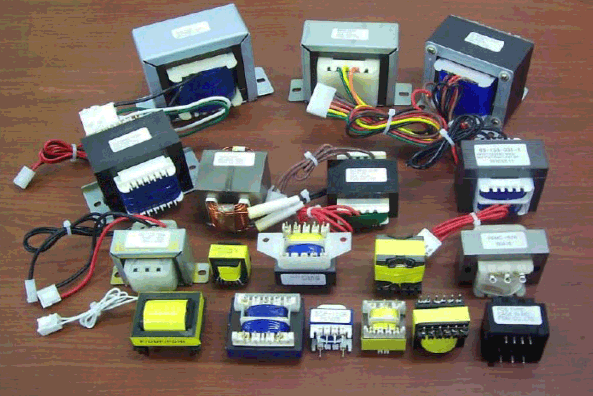
Transformers are an inseparable part of modern technology. A transformer can to step down mains to workable voltage range or step up to power a high end device. Used in CRT screens, tube amplifiers to match the high impedance of tubes to low impedance of the speakers. It almost never has a viable workaround. You need it, and that’s it! Most of the times, you cannot find transformer parameters on it. It is up to the engineer to figure out the parameters. Lets make an example of how to find some of the parameters of such a transformer.
4. EXAMINING AN UNKNOWN TRANSFORMER:
First you need to make an eye inspection. Check out its size, its core type, look up in what part of the equipment it was in previously, to get an idea of its type. Also check out the wires. Their thickness will give you a good guess as to which is the primary, and the secondary. Low voltage, high current winding’s typically use thicker wires, and vice versa.
Next, find a safer voltage range to work with, when examining the transformer. Use a known step down transformer, for which you know the output voltage. In our example, we will use a 10V transformer. We will hook it up to the HIGH VOLTAGE SIDE of the unknown transformer. Remember what I said, about finding out the high voltage/low voltage out. The less thick wire is the high voltage side. Okay, so after hooking it up, we measure the secondary on the unknown transformer.
Lets say we measure around 1V. This means the transformer stepped down the voltage a 10 times. From this you can determining the winding ratio. This Is a measure as to how many windings there are in the secondary, in respect to the primary. in this case we have a 1:10 ratio. This means that if you apply 220V on the primary, you will get 22V on the secondary. Next, if you want to use this as an audio transformer for a tube amp, you need to determine the reflected impedance of the load onto the primary of the transformer. It is equal to the square of the turn ratio multiplied by the load. Lets say we have an 8 ohm speaker. Then the impedance will be 10 ^ 2 x 8= 800ohm. The primary side of the transformer will see a load of 800ohm, where the secondary will see a load of 8ohms.
This is one of the uses of transformers, to match the impedance of mismatched circuits. A high impedance tube amp, will not efficiently supply the load current, without such a transformer. This is proven by the Thevenin Maximum Current Transfer theorem, which states that for most efficient utilization of the power of an external source, with finite resistance, the load must have equal resistance as the source, as viewed from its output terminals.
5. DESIGNING YOUR OWN TRANSFORMER:
Okay guys, here goes the real deal. Every engineer has once found himself in a situation where they need a custom designed transformer. Every engineer has a different tactics in designing one. This is what I have trusted over the years, so far without remorse.
- Your design starts with finding out how much power you need out of the secondary of your transformer. This is given by the formula P2=I2.V2. In our example we will assume it to be 50W.
- After knowing the secondary power rating, we need to find out the primary power rating, based on the expected efficiency of the transformer. Typically low power transformers are more inefficient, and for transformers up to 10W, an efficiency of 80% can be assumed. From 10W up to around 50W, the efficiency can be assumed anywhere from 80% up to 90%, and above 50W, the efficiency stays at around 90% (except for highly efficient toroidal cores, which we will not be covering today).
- Next, turn the efficiency percentage into ratio. Just divide it by a hundred. The power required from the primary is given by the formula P1= P2 / Eff (where Eff is the efficiency ratio). For a 50W transformer and a 0.9 assumed ratio, a primary power rating can be assumed to be 55W ( P1 = 50 / 0.9 ) The leftover 5W will be dissipated as heat losses.
- Next, you need to find the needed cross section area of the core, required for the power rating you need. This is given by the very simple formula S= √P1. In our example the core area needs to be S = √55 = 7.41cm^2. Always leave a little extra, for the core, the effective cross section is always lower, than what you measure, due to air gaps when stacking the lamination’s and the overall imperfections of the core. So for our example lets use a core with a cross section of 8cm^2.
- Now, lets use what we have got this far, and calculate the number of turns for the core. By now, you should know what voltage your transformer will be working with, both the primary and the secondary. Lets assume the primary voltage to be V1=220V, and the secondary V2=25V. The formulas that give the number of turns you need are as it follows W1 = 40 x V1 / S and W2 = 44 x V2 / S. This gives us 1100 turns for the primary of our example and 138 turns for the secondary.
- Almost there, now you just need to calculate the wire gauge for the winding’s. I’m European, so I will be working with mm as wire size, and not AWG. The formula is very simple d = 0.02x√I(mA), where the current is in mA. Now you need to calculate the current, which your winding’s will be handling.
- For the primary it is I= 55W / 220V= 0.25A, or 250mA. For the secondary, the current is I = 50 / 25 = 2A or 2000mA. Now you can add those numbers in the formula and we get d = 0.02 x √250 = 0.32mm for the primary and d=0.02 x √2000=0.89mm.
- Its always good to round up to the higher possible size. For instance, a standardized wire size for the primary will be 0.4mm, and for the secondary 1mm
By following these steps you will be able to design your own custom transformer. Hope this tutorial would have been a great use. In case for any suggestions that you want me to add, doubts or feedback’s please use the comment box below 🙂


Hi there
In the number of turn formulas; what are the# 40 & 44? Are they a constant multipliers?
Thanks
Wow this is one of the most impressive article I have ever come across but my question is that….. Is this process also thesame when designing a step up transformer
hello
i need transformer for my project diy amp mono, can you just help me im from philippines
i need a 6 ampere 12 volts
my amp is 80 watts 6 amperes and 12 volts supply
our primary source is 220 volts ac,and we follow the AWG wire code
This is an interesting, well thought out article.
If I may ask, where do the constants 40 and 44 come from when calculating the number of turns on the primary and secondary windings?
I have the same question. So, please…do tell.
Sir your tutorial is to good plz make more tutorial on ARM controller
Sir plz update switching mode power supply yellow transformer that how it’s work along with circuit design and how to made 5v 3a/5a power supply without using transformer sir plz plz
Thank u verymuch
Pls other tutorial about ferrite transformers
We will look into it and post it