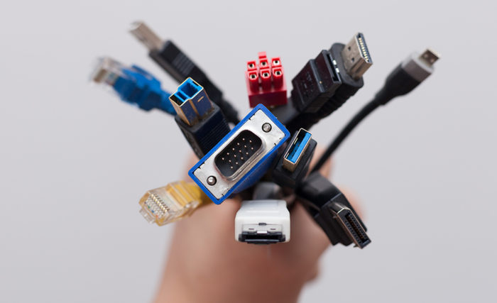
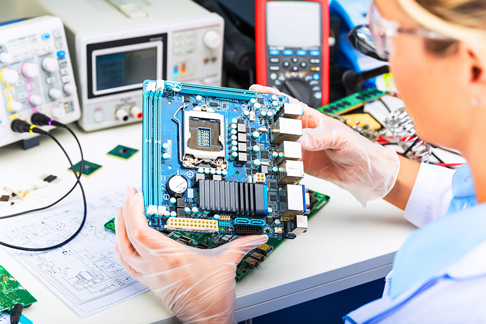
Connectors come in to play when designers want to provide external connectivity to their board. Be it power, digital, analog or high speed signals its important we choose the connector that is designed to fit the purpose. It’s obvious, designers will be most concerned with PCB footprint when choosing a connector however there are other factors that need to be considered in this aspect. Even with the knowledge of commonly used connectors it is common to get confused about the choice of connectors in your PCB. This article list out some of the key factors that a designer should consider when choosing connector for their board.
Price:
Not all connectors are same. Connectors from Molex, Delphi are probably going to cost more than connectors from other brands. We definitely don’t want to design a PCB with a connector only to realize that it is not feasible for the given budget. Account for the cost of connector earlier in the design phase to avoid this bottleneck later in the production.
Polarity protection:
This factor is quite important when you are dealing with power connectors. As a PCB designer we should consider the end user and their way of usage. If there is a risk of improper connection that can spoil the PCB board it’s quite important to add polarized connectors to your design. These polarized connectors will prevent user from connecting the board in improper way thus eliminating the risk of short circuit.
Current rating and Operating temperature:
PCB traces carry current and in turn dissipate heat. But the current carried in a trace and heat dissipated in it varies largely with different PCB boards. It’s a common sight for technicians to witness burnt out connectors when repairing PCB boards. These are most likely due to the poor selection of connectors without considering the current flow and operating temperature of connectors. As a result these connectors melt and board will cease to work. Always consider the maximum current flow in a trace and use connectors that can withstand double the amount of current through the trace.
EMI and ESD shielding:
In high speed PCB designs the signals should be protected from Electro magnetic interferences ( EMI ) and Electro static discharge ( ESD ) to achieve higher speed rates. This calls for special shielded connectors that will protect the signals in PCB while maintaining its integrity. These type of shielded connectors can cost more and designers may need to account for that in their design. If you are using PCB assembly services then you need to check with your manufacturer to see if they support the specified connectors.
Size and Footprint:
We have saved this for the last since this is an obvious factor but still need to be stated out. Always use connectors that fits your board size and functionality. Factors such as pitch size, spacing and connector type can affect the size and footprint of connectors in a PCB. Plan in beforehand and pick the right one that suits your board size and functionality.
We will update this article with more information in the future. Hope this article was informative to you. If you think we missed out any key factor that should be included here, please let us know in the comments section below.

