Function generators (aka FG’s) are widely useful in many audio and analog circuits. FG’s are capable of generating Sine, Square, Sawtooth and Triangle waveforms. But not many electronic hobbyists can afford to buy FG for their experimentation purpose. This function generator circuit will come in handy for those who want to build a simple cost effective Function generator by their own.
WORKING OF FUNCTION GENERATOR CIRCUIT:
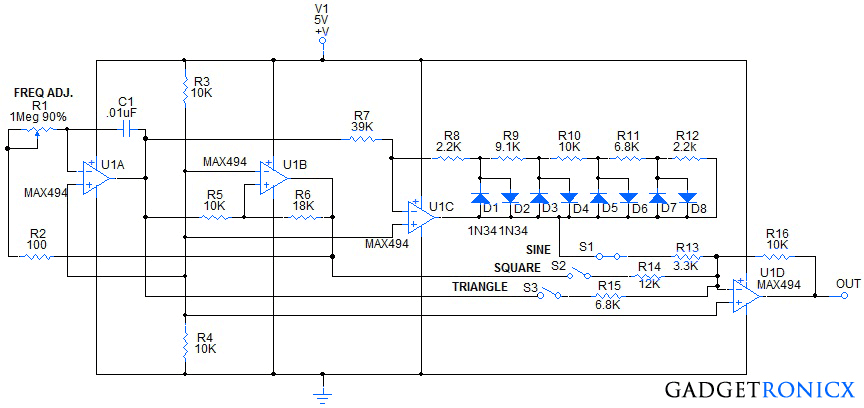
This Circuit was built around a Quad op amp IC MAX494 which takes less supply for operation. U1A and U1B form a triangle wave, square wave oscillator, respectively. U1B has hysteresis provided by R6 to input U1Bin+. The output of U1B connects through R2 and R1 (Frequency Adjust pot) to the input U1Ain-. C1 connects from the output of U1A to U1Ain-. This configuration causes U1A to work as an integrator.
When the input feeding U1Ain- is less than the reference voltage, the output of U1A ramps up. The output of U1A is connects through R5 to input U1Bin+. When the voltage at U1Bin+ is greater than the reference voltage at U1Bin-, the output of U1B goes high. This raises the voltage at U1Bin+ causing U1B to switch states. Since the output of U1B is higher than the reference voltage at U1Ain+, the output of U1A begins to ramp down. When the output of U1A through R5 pulls the input U1Bin+ lower than U1Bin- reference, U1B output switches low. This causes U1A to again begin ramping up until the output of U1A causes the input U1Bin+ to go higher than U1Bin-, and the process repeats in an oscillating manner.
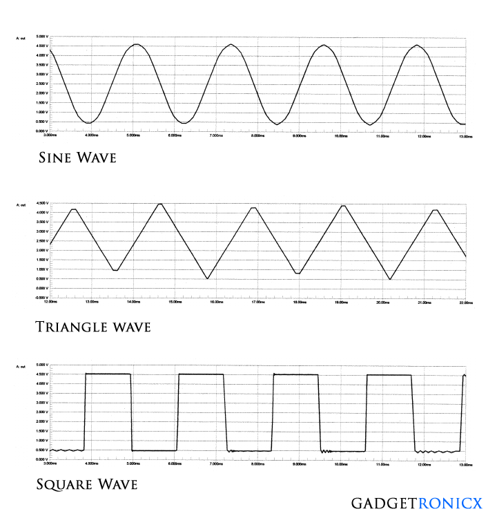
The output of U1A is a triangle wave. The output of U1B is a square wave. To produce a pseudo-sine wave, the output of U1A is connected by R7 to input U1Cin-. The network of resistors R8 – R12 and diodes D1 – D8 clip or reduce the gain of U1C, progressively, as the triangle amplitude increases. This reduces and rounds off the tip of the triangle wave to produce the pseudo-sine wave.
The outputs of U1A, U1B and U1C are connected through R15, R14, and R13 to the input U1Din-. R18 provides the appropriate feedback for controlling the output level of U1D. By substituting a 10K pot for R16, the output signal level of U1D could be adjusted from 0 to Vmax. A selector switch for S1, S2, S3 could be used to select the desired output type of waveform.
OUTPUT WAVEFORM:
NOTE:
- A selector switch, to select different values of capacitance for C1 ( .1uF, .01uF, or .001uF), could be added to increase the frequency range of the function generator.


it helped many thanks!
good circuit wanna build one but before that what should i do to generate sawtooth along with three basic wavforms
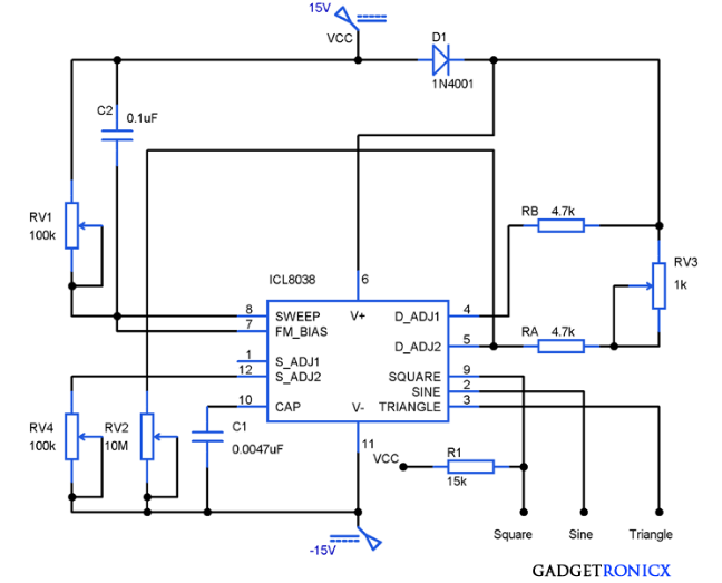
Kindly refer this link for the advanced version of this circuit
Advanced Function generator circuit