 |
|
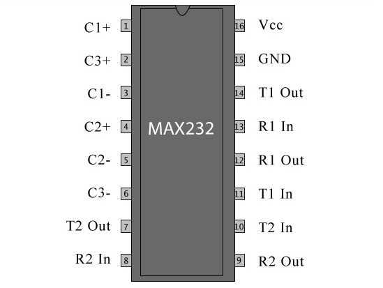
| MAX232 IC Pin diagram |
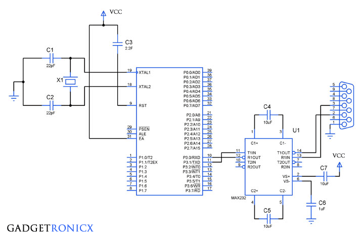
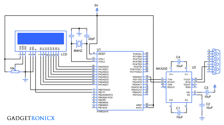
MAX232 is a widely known IC used for establishing serial communication between Microcontrollers and Personal Computers (PC). This IC is used to convert TTL/CMOS logic levels to RS232 Logic levels during the process of serial communication. Usually a Microcontroller operates at TTL (Transistor Transistor Logic) of about 0-5V whereas a PC works on RS232 standards that is (-25 to +25V). So it is not possible to interface a PC directly with a Microcontroller and this is exactly where a MAX232 IC comes into Play.
PIN DESCRIPTION OF MAX232:
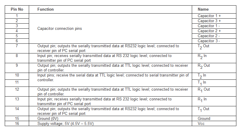 |
| Pin Description table of MAX232 |
WORKING OF MAX232:
MAX232 offers a intermediate link between the Microcontroller and your PC. The transmitters of this IC will convert the TTL/CMOS input level into RS232 voltage levels. The receiver pins are capable of taking input around -30V to +30V. Meanwhile each receiver converts RS232 inputs to 5V TTL/CMOS logic level which was fed into the Rx pin of a Microcontroller. So summing up this IC acts as a intermediator by converting the voltage level of signals.
The IC is capable of supplying RS232 standard voltage logic levels by means of a single 5V power supply. This was done by means of a capacitive voltage generator used within that IC. So we need to connect three external capacitors whose value range from 1uF to 22uF. The capacitors are meant to be connected across the pins C1+ & C1-, C2+ & C2-, C3+ & C3-.

