 |
| FM transmitter Circuit |
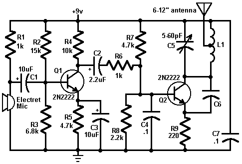
FM circuit holds a significant position in wireless communication.This circuit uses a single transistor transmit noise free FM signal to the distance of about 50-300 meters.The transmitted signal from the transmitter can be received by means a simple receiver circuit which have the facilities of FM.
WORKING OF FM CIRCUIT :
The above circuit was very simple and uses only 9V and a mike for feeding audio input to the transmitter circuit.The circuit can be divided into three parts for simple understanding that is oscillator,Modulator and amplifier.
The Q1 acts as the amplifier, it amplifies the audio signal from the microphone.R2-R4 are there in the circuit in order to set the working point of the transistor.C1 and C2 in the circuit acts as blocking capacitors so only AC signal can go through them.
The Tank circuit with C5,C6 and L1 together with the Transistor Q2 forms the Oscillator part in the circuit.The resistors around the Transistor Q2 set the working point for Q2 and to limit modulation in FM band which is 80-130 MHz.
The length of the antenna should be long so that the transmission will be efficient and receiver would be able to pick noise free signal.Transmitter circuits are very fun to work on, try it out and post your opinions about this circuit.

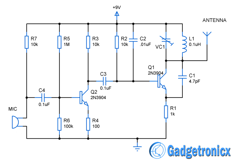


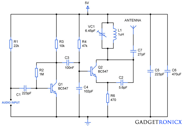


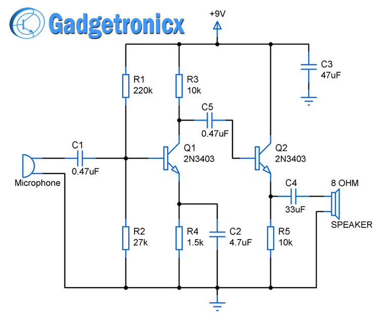
Sir,some time resistor are used in 1k and in this time other part of circuit are used in ohm,pico,value why this value change
Hi Muhammad,
Am not sure if I got you right. The schematic remains the same it didn’t change.