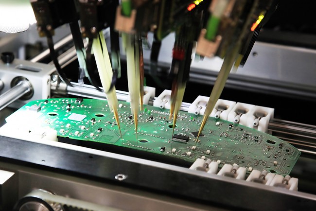
Printed Circuit Boards (PCBs) are critical to any electronic product. Any error in PCB design or assembly can lead to product failure. With the growth in technology Electronic engineers and manufacturers are under pressure to design and produce smaller, flexible, and more efficient PCBs to meet the demand for wearable devices, smartphones, 5G, Internet of Things (IoT), etc.
To increase consumers confidence in the soundness of the final product, manufacturers must demonstrate that the PCB not only meets regulatory safety requirements but can also perform reliably without any fault in components and parts in PCB.
Manufacturers used different types of PCB testing methods to produce reliable PCBs.
Objectives of PCB test
PCB tests have three primary objectives:
Error identification: PCB testing helps to identify problems in PCBs. If the issue lies in manufacturing, functionality, or elsewhere. PCB testing can pinpoint where there are errors so that designers can adjust as needed.
Timesaving: PCB testing serves as an early-stage time-saving measure. Testing also enables designers to identify significant issues during the prototyping stage.
Cost reduction: PCB testing plays a crucial role in reducing wasteful production of defective products by applying prototypes and small-scale assemblies to test products.
That is why PCB tests are most critical step in PCB manufacturing.
What is PCB test?
PCB testing is a primary requirement in the PCB assembly industry, and it involves checking for specific criteria. Here are some criteria that PCB tests must confirm to ascertain if they meet design requirements.
Lamination -This component determines the life of a PCB. It focuses on the strength of the laminate to peel by force or use heat.
Copper Plating -This criterion tests the quality of the copper used to laminate the plate to provide conductivity. They analyze tensile strength and elongation in detail.
Weldability – Wetting or how well a surface accepts liquid solder is the concern of this part of PCB testing. This criterion is essential because it determines if the components can be firmly attached to the board.
Cleanliness – This is PCB’s ability to resist environmental elements such as moisture and corrosion. Includes PCB’s analysis before and after being subjected to various environmental conditions.
Solderability – Testing the solderability of the material is essential for a PCB as it ensures that components can be firmly attached to the board.
Environment – Many PCBs operate in humid climates, so a standard test for PCBs is water absorption.
Electrical – The conductivity of the PCB to allow for minimal leakage of electrical currents.
Hole Wall Quality – This ensures the hole walls do not crack or delaminate as the PCB functions under field conditions.
Types of PCB test
Various types of PCB tests are available in the industry today, but each PCB test has its pros and cons and its best applications. It is often the best practice to be aware of these tests to choose the most suitable one for your specific needs.
Visual Inspection
This manual form of testing relies on the inspector’s visual ability, sometimes aided with a magnifier to see errors within the components installed on the PCB.
However, this is a basic form of inspection, and its efficiency has limitations as it is easy for the inspector’s eyes to miss some defects.
Automated Optical Inspection (AOI)
The use of high-resolution cameras plays a vital role in this type of test. The images produced by the cameras are compared with standard templates of good PCBs to identify any flaws.
Like visual inspection, AOI is concerned with surface flaws but with greater accuracy than visual inspection.
Flying Probe Testing (FPT)
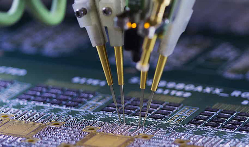
This test makes use of a flying probe test machine which assesses PCBs for errors like misaligned components, passive parts, and voltage reading for components.
Automated X-ray Inspection (AXI)
AXI uses X-ray radiation to detect internal and surface flaws as the test sample absorbs the radiation.
This unique feature of the AXI makes it a perfect tool for testing the most modern PCB mounting technology that features tightly packed components, including SMT, BGAs, SMDs, and SMCs.
Functional Testing (FCT)
This check is the last phase of the testing procedure used as a final quality check for products before moving out for distribution.
In-circuit Testing (ICT)
This test suits large batches of products using PCB test points, and it is often for checking faulty circuit connections either due to missing solder or over-soldering. It can also identify misaligned elements and other soldering irregularities.
Burn-in Testing
This method is a destructive test that simulates extreme conditions that are beyond the design criteria. The essence is to know the failure mode of the PCBs when subjected to harsh conditions in the field.
Difference between types of PCB test
The different types of tests mentioned above have uniqueness and specific applications that make them different from other test types.
Visual Inspection is most suitable for devices with significant components and uncomplicated designs. It is only effective for small scale production and does not need to set up expensive equipment. However, the possibilities for error can be high as tightly packed elements become hard to inspect.
Automated Optical Inspection (AOI) is more accurate than visual inspection, is suitable for large scale production and can fit within the production line to conduct early tests during production. Still, AOI is not adequate for tightly packed PCBs.
Flying Probe Testing (FPT) is a cheaper and faster way of testing small boards with tightly packed components in small or medium-sized production. However, FPT might not be able to detect faults like voids and excess solder.
Automated X-ray Inspection (AXI) is highly suitable for intricate board assembly with high-density components. It also has a very high detection rate for defects, even for high volume manufacturing but often requires highly trained personnel.
Functional Testing (FCT) is best for small scale production but is customizable, mainly when used with other testing methods.
In-Circuit Testing (ICT) is effective when testing large scale production with a fault detection rate of up to 98%. However, the testing equipment can be expensive and hence not suitable for small scale manufacturing.
Burn-In Testing is often deployed for devices in extreme field conditions where device failure is undesirable especially military and medical devices
Conclusion:
PCB tests have become necessary in the electronic manufacturing industry to ensure that the devices are manufactured to meet the highest quality standards.
However, the type of test required to ascertain the quality of your PCB will depend on the scale of production. It depends on the variety of mounting systems, and the density of installed components and other factors.
Therefore, it is worth noting the points mentioned in this article to help you decide the best suitable method for testing your PCBs.

