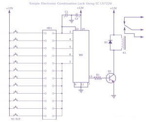
This is the circuit diagram of a simple electronic combination lock using IC LS 7220.This circuit uses a relay for controlling any type of device when the combinations of four digits are pressed.Keypads are used as input here to enter the digits and the correct combination will activate the relay and the door or deice can be operated.
WORKING OF ELECTRONIC COMBINATION LOCK CIRCUIT :
The combination can be set here by connecting the appropriate keys to the pins 3,4,5 and 6 of the IC through Header.Unselected keys are connected to the pin 2.For example if 4568 is your combination then it is to be connected to 3,4,5 and 6th pins and rest of the keys are connected to pin 2.Thus any four key combination can be created using this.
The 2nd pin of this IC was reset so whenever any other keys connected to pin 2 is pressed it will reset the device and the digits have to be re-entered.When the correct combination is pressed the output will be activated for a preset time determined by the capacitor C1.Increase C1 value to increase on time.Using this circuit you can really construct a high efficient lock system.

What is for HD1, I mean what device it is? No reference about it, no pin number.
Thank you for posting the great content…I was looking for something like this…I found it quiet interesting, hopefully you will keep posting such blogs… cell phone detection
nice
Buy our best Electronic Jammer and Blocker in Delhi India, Wireless Jammer, Cellular Phone Jammer, Mobile Signal Jammer in Delhi from our Spy Store.More info visit our website http://www.mobilejammer.in/MOBILE-JAMMER-IN-INDIA-DELHI.html
Thanks for article . tomorrow is my exam of BEEE and this topic is very important .so thanks for sharing this .
interative whiteboards
How can i make 3 digit combination lock using ic. The 3 digit password should display on 3 seven segment leds.