 |
| Electronic Combination lock PIC Mircocontroller |
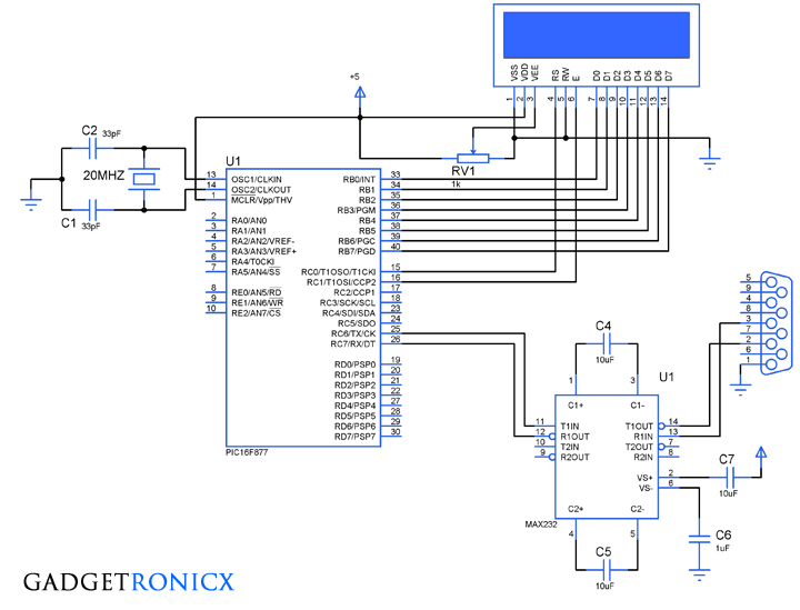
Electronic code locking system is extremely useful in protecting our precious possessions and can be installed anywhere with bit of engineering in it. We are widely familiar with the Password based e-locks and might have installed in our house. But we are going for Electronic locks made by any company when you can make one by your own.
This project demonstrates you how to make a PIC microcontroller based simple digital lock and also explains the programming behind it.
WHAT YOU NEED:
- PIC 16F877 Microcontroller
- 4×3 Keypad – Key Input
- 16×2 LCD – Status Indicator
- 5V Relay – Activator
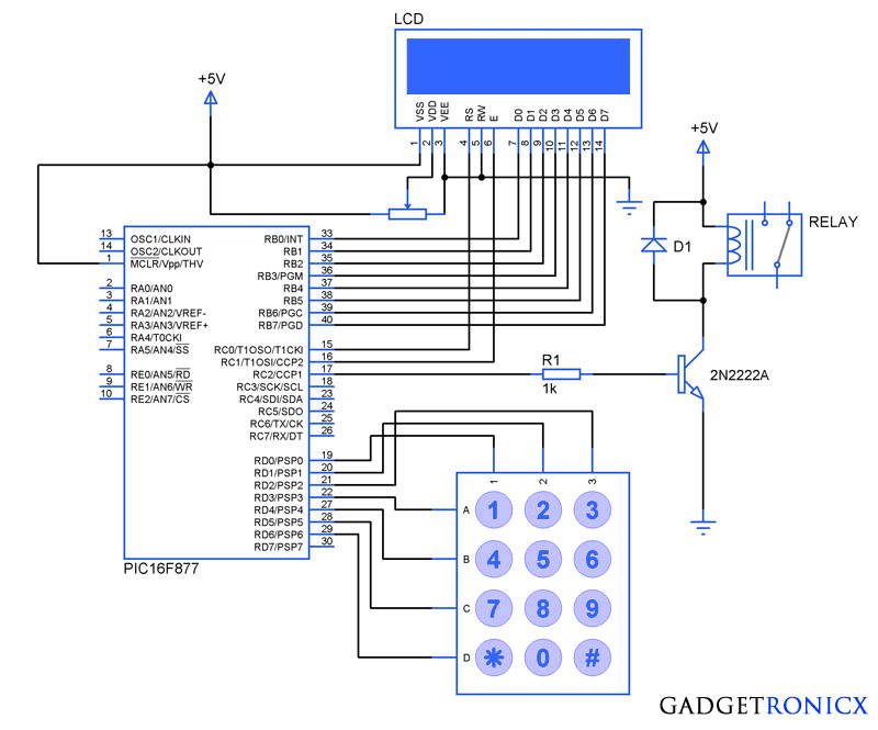
Additionally you need a POT which is used to adjust the contrast of the LCD, A transistor to drive the relay since the current obtained from a Pin of Microcontroller is very less. A diode to prevent the reverse flow of current which might damage the controller.
DESIGN OF ELECTRONIC CODE LOCKING SYSTEM:
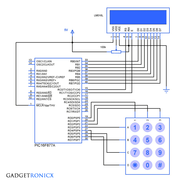
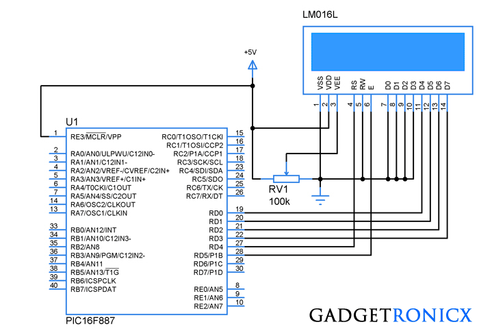
The design of the above Embedded Project is pretty straight forward, you need to interface a LCD to PORT B and Keypad to the PORT D of the Controller. If you are not familiar with it then i suggest you to go through this Interfacing LCD and Keypad with PIC Microcontroller. Now lets see how the system is designed to work as a Locker.
- “*” Key – This key is meant to initialize the system, when the system is turned ON the Controller will scan only this key and pressing this key will enable you to enter the password for your locker.
- “#” Key – When you are done with your locker , you should press this key which will turn off the system and turning off the relay as well.
The remaining keys are meant to feed the character values to the Microcontroller and in turn the Microcontroller will analyze the characters. Based on the Pre defined password in the Controller it will compare the input with it. Thereby it will recognize the correct or incorrect password input.
CODE:
#include<16F877.h>
#include<stdio.h>
#bit led=0x05.0
#bit TRIS_led=0x85.0
#byte lcd=0x06
#byte TRIS_lcd=0x86
#bit rs=0x07.0
#bit TRIS_rs=0x87.0
#bit en=0x07.1
#bit TRIS_en=0x87.1
#bit relay=0x07.2
#bit TRIS_relay=0x87.2
#bit C1=0x08.0
#bit C2=0x08.1
#bit C3=0x08.2
#bit R1=0x08.3
#bit R2=0x08.4
#bit R3=0x08.5
#bit R4=0x08.6
#bit TRIS_C1=0x88.0
#bit TRIS_C2=0x88.1
#bit TRIS_C3=0x88.2
#bit TRIS_R1=0x88.3
#bit TRIS_R2=0x88.4
#bit TRIS_R3=0x88.5
#bit TRIS_R4=0x88.6
void display(unsigned char a,int b);  //LCD subroutine
char keypad();                               //Keypad Subroutine
void check();                                 //Password check routine
char password[5]={"7196"};         //Predefined password
char pswd[5];
unsigned char open_msg[15]="Enter Password";
unsigned char welcome_msg[8]="Welcome";
unsigned char close_msg[15]="Wrong Password";
char c;
int flag,i,count,j;
void main()
{
   TRIS_lcd=TRIS_en=TRIS_rs=TRIS_led=TRIS_relay=0; //Directions set
   TRIS_R1=TRIS_R2=TRIS_R3=TRIS_R4=count=0;
   TRIS_C1=TRIS_C2=TRIS_C3=1;
    while(TRUE)
    {
     c=keypad();
     {
     if(c=='*')                                    //Initialize condition
     {
     flag=1;                                       //Flag set to scan other keys
     count=0;
     display(0x01,0);
     display(0x38,0);
     display(0x0f,0);
     display(0x80,0);
     for(i=0;i<=13;i++)
     {
     display(open_msg[i],1);
     }
     display(0xc0,0);
     }
     else if(c=='#')                         //Turning off condition
     {
     count=0;
     relay=0;
     display(0x01,0);
     display(0x0c,0);
     }
     else
     {
     display('*',1);
     pswd[count]=c;                   //Storing input in new arrays
     count=count+1;
     check();
     }
     }
   }
}
void display(unsigned char a,int b)
  {
    lcd=a;
    rs=b;
    en=1;
    delay_ms(10);
    en=0;
    delay_ms(10);
  }
char keypad()
 {
  if(flag==0)                            //Waiting for Initialization
  {
    while(TRUE)
    {
     R4=1;
     R1=R2=R3=0;
     if(C1==1)
      {
        while(C1==1);
        count=0;
        return '*';
      }
     if(C3==1)
      {
        while(C3==1);
        count=0;
        return '#';
      }
   }
 }
else if(flag==1)
{
while(TRUE)                      //Keypad scan
{
R1=1;
R2=R3=R4=0;
if(C1==1)
{
while(C1==1);
return '1';
}
if(C2==1)
{
while(C2==1);
return '2';
}
if(C3==1)
{
while(C3==1);
return '3';
}
R2=1;
R1=R3=R4=0;
if(C1==1)
{
while(C1==1);
return '4';
}
if(C2==1)
{
while(C2==1);
return '5';
}
if(C3==1)
{
while(C3==1);
return '6';
}
R3=1;
R1=R2=R4=0;
if(C1==1)
{
while(C1==1);
return '7';
}
if(C2==1)
{
while(C2==1);
return '8';
}
if(C3==1)
{
while(C3==1);
return '9';
}
R4=1;
R1=R2=R3=0;
if(C1==1)
{
while(C1==1);
return '*';
}
if(C2==1)
{
while(C2==1);
return '0';
}
if(C3==1)
{
while(C3==1);
return '#';
}
}
}
}
void check()
{
if(count>3)                 //Input exceeds count 3 will execute comparison
 {
 flag=count=0;
 j=strcmp(pswd,password);     //Comparison of input and Predefined pswd
 if(j==0)
   {
      relay=1;                         //Turning relay on
      display(0x01,0);
      display(0x80,0);
      for(i=0;i<=6;i++)
      {display(welcome_msg[i],1);}
   }
 else
   {
      relay=0;
      display(0x01,0);
      display(0x80,0);
      for(i=0;i<=13;i++)
      {display(close_msg[i],1);}
   }
 }
}
NOTE:
- You can add additional security by adding trial above code.
- It can be done by making the trial value to increase for every wrong password input and checking the condition whether it exceeds the desired trial value.
- Once it exceeds the desired trial value disable the keypad scan and display message “No more trials” in the LCD.
- You can also add speaker to sound a alarm once the trial exceeds to alert the people nearby.


Hello, frank, I want to ask you about the name of all the components that you use because I can’t find it in proteus.
Haziq,
You can find the component name in What you need section of the article.
I am facing a problem in taking value from the keypad. When I click one key, it takes its value 4 times and displays the wrong message. I tried changing delays but that didn’t work. How can I rectify this?
Hetvi,
It happens with the Physical switches because of its irregular contacts. This can appear to be multiple inputs to microcontroller. Use pull down resistors with RD0, RD1, RD2 pins of PIC controller. That should fix this issue.
can u please help me resetting the password and user defining a new password for this project
Resetting has to be done in the code. Including the feature in the code can make the code bulky and cumbersome.
can you give me bluetooth code to send e msg to my cell phone when the ultrasonic detect something !!!
What you need requires BT module, GSM module and Ultrasonic module. A whole new circuit and code is required to do that.
hello frank, at what frequency is the micro controller working at ? 8MHz or 4MHz
Kwaku,
8Mhz
I have connected everything but nothing is showing on my LCD.. can you please share the proteus drawing
Not sure what the problem is, Have you programmed your MCU successfully?
yeah , I copied and pasted the code on the website, it compiled successfully and i proceeded to draw the circuit on proteus.. yet when I run the simulation on proteus I get nothing on the LCD although I can observe changes on the terminals of the LCD
it working.. thanks for the help Frank
Thanks, Glad you got it figured out 🙂
dear kwaka
i have faced same problem, can you please help me. display didnt show anything.
hi Donald
I need help to add a password on my projects;;;; keypad and LCD interfacing a 16F877A PIC;;;;; with Micro C pro for PIC language
Rabah,
Please go ahead, what help you need?
sir, am getting errors if I run it in MPLABx software, could you tell me any other software in which i can run this.
Rahul,
Use CCS compiler
Frank I Need your help on a project. contact me hamzainam459@gmail.com
May i get assembly language of this program please.
Woon,
Am sorry, am not familiar with Assembly code writing.
hi..can i know what type of diode did yo used??
1N4001 will fit the purpose