Door or Window alarm circuit have been used widely in many homes to detect intrusion. A simple search in internet might fetch you lot of alarms for you to buy. But making your own alarm will be something special and that’s the purpose of this article. For this article i have reverse engineered a window alarm gadget to obtain the schematic design.
COMPONENTS REQUIRED:
- Piezoelectric element
- Transistors
- Resistors
- Capacitors
- Microcontroller.
PICKING AN MICROCONTROLLER:
This circuit uses an Microcontroller to detect the input voltage and produce square wave (Explained below). Any MCU with ADC inbuilt will suit for this purpose. Using big MCU’s will be an overkill so i have chosen Atiny85 for this circuit. And i have used Arduino IDE to program it. Here is a step by step instruction to program Atiny85 using Arduino and its IDE.
WINDOW ALARM CIRCUIT EXPLANATION:
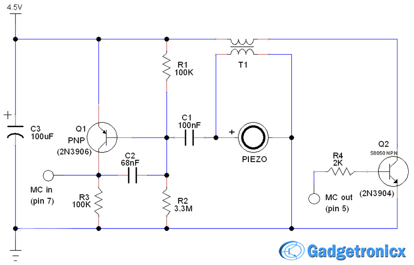
This circuit uses a Piezoelectric element which should be sticked to a window or door. When someone taps on the window or tries to open it, the vibrations will cause the piezoelectric element in the circuit to vibrate and thus in turn will produce a voltage. This voltage is referenced to ground, so it pulls the base of the PNP transistor Q1 to ground and cause it to open which triggers the Microcontroller (Omitted in the design for simplicity).
Now once voltage rises in the pin 7 of the Microcontroller it produces a square wave in its pin 5. This square wave is fed into base of the transistor Q2 which turns the transistor ON and OFF. This triggers the coil T1 to develop an alternating voltage across its terminals. This alternating voltage will feed the piezo element which in turn produces the alarm sound.
Do note that Piezo elements only work with AC ,so higher the turns in the coil better its functionality will be. The alarm can only be turned off by cutting the power supply to the whole circuit. Always turn the circuit ON once you set the circuit to a window or door.
ARDUINO CODE:
This is the code i have used.
int sensorValue = 0;

void setup()
{
  pinMode(5, OUTPUT);
}

void loop()
{
  sensorValue = analogRead(7);
  if(sensorValue>0)
  soundalarm();
  delay(10);
}

void soundalarm()
{
  digitalWrite(5, HIGH);
  delay(100);
  digitalWrite(5, LOW);
  delay(100);
}
If you intend to use any other MCU. Just use this algorithm to code.
- Read analog input voltage from desired pin and check if the ADC value is greater than zero. Run this in an infinite loop.
- If ADC value is greater than zero, turn a digital pin on and off with 100 milli seconds interval.

