Stereo Amplifiers are quite handy in places where we need to amplify the input signals to make it audible for all. Whether it is for a party, a meeting, or just to listen to full Hi-Fidelity, this amplifier will do a perfect job. This Stereo amplifier circuit is easy to build and will provide amazing audio power and extremely low total harmonic distortion. It is much cleaner than anything I have seen on the market using standard audio IC’s.
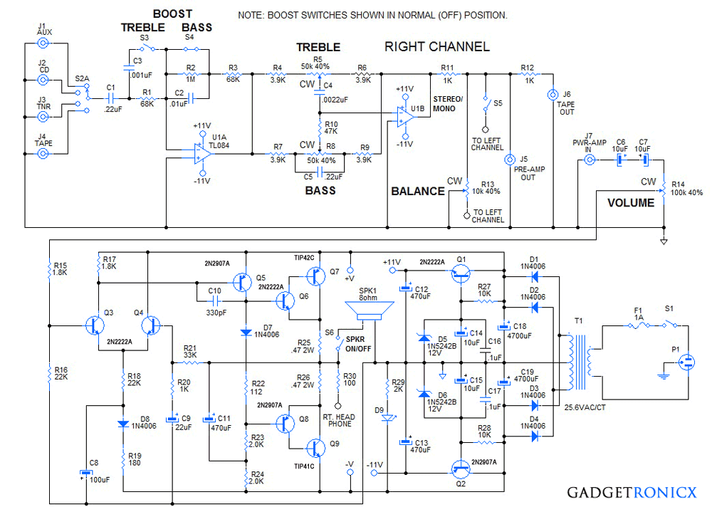
STEREO AMPLIFIER CIRCUIT DIAGRAM:
WORKING DESCRIPTION:
The pre-amp section uses two op-amps, U1A and U1B to provide treble and bass boost at low volumes and treble and bass controls for tailoring the sound to the user’s preference. Selector switch S2A is a 2P4T, ( 2-pole, 4-throw (position)) rotary type to select from one of four line level inputs, (AUX, CD, TUNER, TAPE). They are coupled to U1A via C1, R1. Switches S3 and S4 are DPDT (double pole, double throw) slide switches that select for treble and bass boost.
As shown, they are in the OFF (no boost) position. R2 and C2 are shorted out by S4 canceling the bass boost. S1 is open which defeats the treble boost. R1 and R3 form a unity gain invertor/buffer and feed the signal to the treble/bass control network of U1B. If switch S3 is closed, then C3 is in parallel with R1 and boosts the treble gain at a break frequency of 2.34 KHz. If switch S4 is opened, then the feedback loop has an additional gain 16, and a low pass break frequency of 234 Hz.
The tone circuitry, Treble and Bass are enabled via U1B and the feedback network R4 – R9 and C4, C5. The Bass control has a break frequency around 190 Hz and a gain of around 16 db. The Treble control has a break frequency around 1500 Hz and a gain of 15 db. The output of U1B is connected by R11 to the balance control which has a grounded wiper. This decreases or increases the output of the Right and Left channels in an opposite manner to balance the signal level of a common input to both channels.
Resistor R11 connects to J5, the Pre-Amp Output jack and through R12 to J6, the Tape Output jack. Jack J7, is the Power-Amp input jack. A jumper cable must be connected from jacks J5 to J7 to pass the Pre-Amp signal to the Power-Amp. If desired, an effects processor, graphic equalizer or other audio processor can be inserted in the signal chain between jacks, J5 and J7, to further enhance the signal. Switch S5, when closed, combines the Right and Left channels for Mono operation. This is useful for a single channel mic input, or mono input, to enable sound to come out of both speakers, (Right and Left).
The Power-Amp circuit amplifies the line level signal at jack, J7, to power the 8-ohm Speaker. The signal is passed through C6, C7, which are wired to form a 5 uF non-polar capacitor, to the volume control, R14. The wiper of R14 passes the desired signal level through R15 to the positive input, (base of Q3), of the power op-amp stage.
Q3 and Q4 form the differential input pair of the power op-amp. D8, C8, R18, and R19 isolate the negative voltage rail and act as a current source to transistors, Q3, Q4. Transistor Q5, performs as a level shifter to drive the quasi-complimentary, cascode output pairs formed by transistors Q6, Q7 and transistors Q8, Q9 respectively. Diode D7 and R22 provide the correct bias voltage separation to provide about 10 to 20 mA of idle current through the output stage transistors and resistors R25, R26. This ensures that there is no cross-over distortion in the output signal, because the cascode output transistor pairs are actively conducting at the crossover transition.
Capacitor, C11 and resistors, R23, R24, form a bootstrap bias network that provides the negative bias to cascode transistor pair Q8, Q9, during the negative half cycle of the signal waveform. The Power-Amp stage gain is set by R21, R20 and C9. Except for frequencies lower than 8 Hz, C9 can be ignored in the GAIN equation.
Thus a .5 volt peak input voltage will yield a 17 volt output peak voltage which is ideal for the +/- 18 VDC supply. Transistors Q1, Q2 are connected as emitter follower voltage regulators to supply +/- 11 volts to the TL084 pre-amp IC.
LED D9 and current limiting resistor R29 indicate when the stereo is ON. The main power supply consists of transformer T1, 25.6 VAC, center-tapped, at 2 to 4 Amps. D1 – D4 form a full-wave bridge rectifier which is filtered by capacitors, C18, C19. Switch S6, Enables or Disables the speakers. Resistor R30 reduces the output before it is connected to the stereo headphone output jack (not shown).
NOTE:
- Only the Right Channel Pre-Amp and Power Amp are shown, the Left channel is the same.
- Use dual controls for Treble, Bass and Volume. Use DPDT slide switches for Treble and Bass Boost.
- A 2P4T (2-pole, 4-throw, position) rotary switch to select sound signal source. Treble and Bass controls are linear taper.
- The volume control is audio taper.
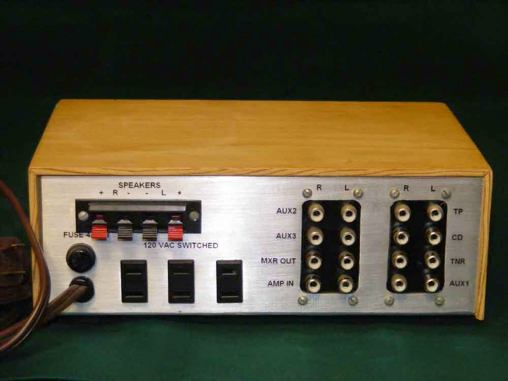
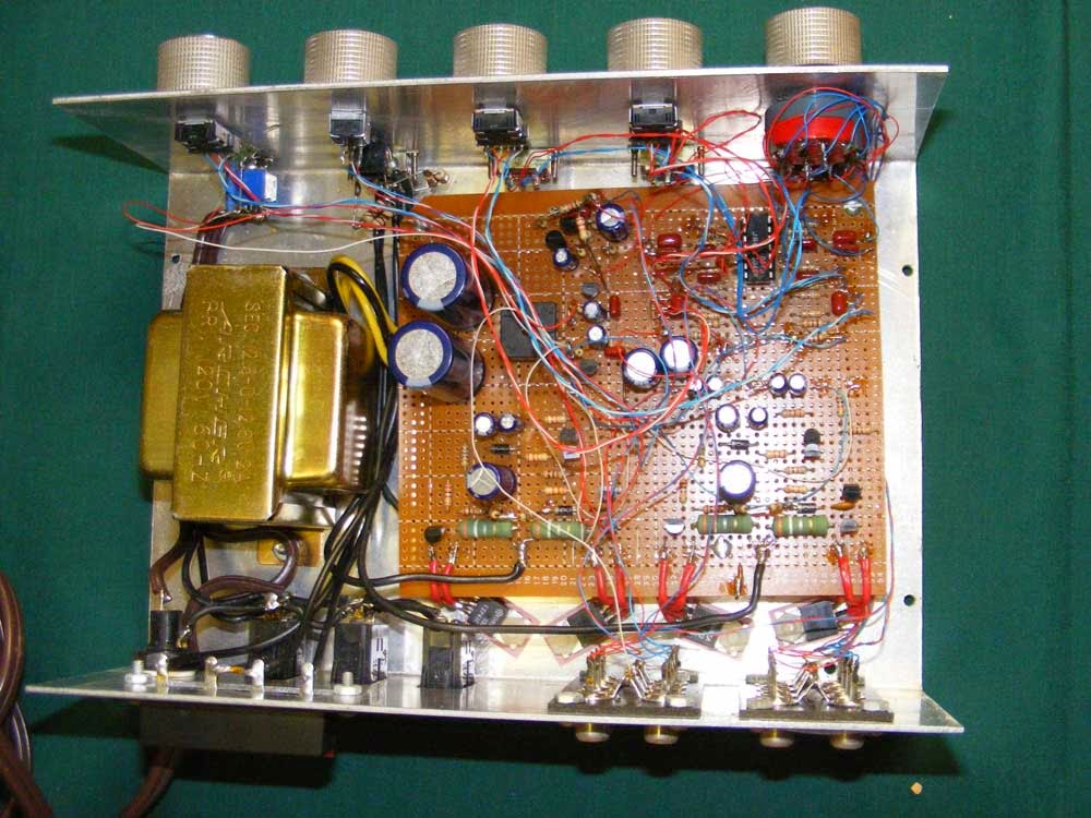
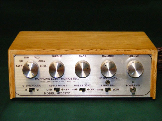
STEREO AMPLIFIER:
 |
 |

Olá, obrigado por este post. Posso usar um trafo de 13-0-13 Vac 4A ?
Hi. I cannot design circuits, but I do understand what most components do. I would love to build this amp. I am in the uk so would have to sort out the correct transformer. But I have one question. Do all the transistors require any heatsinks pleae?
Mike
In general
The pre amp side doesn’t
The power amp side depends on the power output but anything over 10 Watts I would mount power transistors on a heat sink
A good way to learn is understanding the amplifier classes
Build a 3w amp .. play with it
The slowly work your way up.
( low power output makes for cheap fixing of mistakes)
Plus soldering cheap transistors is good way to practice.
Once you gain confidence the projects grow.
Side note.. it is tempting to just get a board a wire it up .. but little is learned that way.
Thanks, sir Hoffman. I’m really trying to build on electronics knowledge so thanks for your help. Also, I’m really anticipating the A-B amp. Perhaps it’s modifiable to play from phones as well. Please let me know when you are posting that one if you have the time.
Hi, I am new to electronics and I am going to build this. My question is, Do I just build the whole schematic twice to get the left and right channels except the power supply and then connect them accordingly? I noticed on the open case photo there is only 1 TL084 chip. So do I just tie the left channel in where there would be a TL084 for the left channel? Thanks.
Hi Vincent, The TL084 is a quad op-amp. Two of the op-amps are used for the right channel, and two are used for the left channel. The output power amplifier and the pre-amp circuits need to be duplicated for the right and left channels. The power supply and regulators are just built once as shown in the schematic diagram. The treble, bass and volume controls are tandem, dual units. The treble and and bass controls have a linear taper. The volume controls have an audio taper. Let me know if you need further information.
Thank you for you reply sir. Is there a link to a parts list just to make it a little easier to get everything together. Or is there one and I am missing it? thank you again!
Hi Vincent. There was no parts list made for this article. The schematic lists all of the parts and their values. The aluminum electrolytic capacitors should be 25V or 35 V. The small signal caps can be 25V or higher (I recommend metalized film caps for all signal chain capacitors). C11 must be 35V type. switch S3R-L (Treble Boost), s4R-L (Bass Boost), and S6R-L (Speakers ON-OFF), are miniature DPDT slide switches. S1 (Power On/OFF) is a SPST toggle, slide, or rocker switch, 120VAC @ 3A or more. S5 can be an SPST slide switch, or you can use a switch like S3, S4, or S6 and wire it as SPST, or DPST switch (Mono/Stereo). S2 is a 2-Pole, 4-Position rotary switch (Selects input an input source). The Treble and Bass controls, R5 and R8 are dual linear taper 50K ohm types. The volume control, R14 is a dual 100K ohm, audio taper type. The Balance control is a single 10K ohm linear taper type. The switched power receptacles are optional but come in very handy for added preamps, sound effects, turntables, CD players, etc. The transformer is 120VAC to 25.6 VAC @ 3 amps. The one I used was from Radio Shack and I don’t know if it is still available. A similar unit should be able to be found. Hope this helps you with your question. Regards, Ron
Thanks again Ron. I appreciate your timely response and the details you put into it. I just about have all the parts and was able to get a transformer from Triad Magnetics that will do. Take care!
Greetings from Georgia, USA. This is an old but interesting post. I’ve been studying this circuit for few days and I will like to build it. I’ll like to ask few questions before order components. Is this circuit a 30 watt per channel or 30 watt total? In the diagram, the electrolytic capacitors stated the uf value but missing the recommended voltage, will C18 and C19 68Volt will be ok, will 35V for the rest of the electrolytic capacitor will be ok?
Thank you!
Hi Raphael, The stereo with the 25.2 VAC transformer delivers 15 watts per channel, or 30 watts RMS total into an 8 ohm speaker load. If you use 4 ohm speakers, the amp can deliver 30 watts per channel. The transformer for 4 ohm speakers would need to be larger to deliver 3 A RMS @ 25.2 V center tapped. For the existing circuit, 25V electrolytic capacitors for C18, C19 will work fine. Hope this answers your questions. Good luck with the build. Let me know how it turns out.
Hello Ron Hoffman. I want to use this circuit as a simple guitar amp as well. Do you think that can work? how many speakers can be powered? I’d love to hear from you.
Hi Jordan, You can use this circuit for a guitar amp. You of course would only need one channel for the output to power the speakers. If you use two 8 ohm speakers in parallel, that would be 4 ohms. The amp could deliver 30 watts into the 4 ohm load. The transformer would need to be increased to have a secondary rating of 12 VACT (Volts AC center Tapped) @ 4.0 Amps. Also, the left and right channel pre-amps could be combined to provide for two separate instrument input channels.
I have a 55 watt guitar amp circuit and project that I will be publishing here soon. It uses an LM3786 class A-B amplifier module and one clear and one special effects channel that features adjustable distortion and sustain circuits. It is designed for playing at live performances.
Thanks, sir Hoffman. I’m really trying to build on electronics knowledge so thanks for your help. Also, I’m really anticipating the A-B amp. Perhaps it’s modifiable to play from phones as well. Please let me know when you are posting that one if you have the time.
Sir, you mention that the transformer is 25.6V A.C. (diagram), in that case the D.C. output may exceed 30V D.C. so, is the 25V electrolytic condenser safe ?
Babu, The transformer is 25.6 VACT (Volts A/C Center Tapped. Thus, each CAPACITOR sees 12.8 x sqrt (2) = 18.1 VDC. So the 25 volt caps work fine. another way to look at it is to think that the total voltage across the bridge rectifier is 25.6 x sqrt (2) = 36.2 VDC. Since the two electrolytics are in series, they each have 18.1 volts across them. Either way, the 25 VDC rating is well above their actual voltage. Regards, Ron H
Mr. Hoffman; Thank you for your quick response. I’ll gather all components and put this amp together. I will let you know how it goes.
May I ask where I can find the right transformer? I have been looking around for a center tapped 25,4V Transformer, but couldn’t find any. Is it possible to use a 26 Volt or 25,2V transformer or something like that? Thanks!
Yes, Raphael. You may use any transformer that is close to the 25.4 volt CT (Center Tapped), value. I used a Radio Shack transformer rated at 2 amps. I found a unit that would work fine from Mouser Electronics Mouser Part # 553-F8-28 from Triad Magnetics rated at 28 VAC CT @ 3.6 A. It was about $20. Hope this helps you here is the link to the Mouser page with various transformers.
https://www.mouser.com/Power/Transformers/Power-Transformers/_/N-8u9n5?P=1ydfa2lZ1ydfa0aZ1ycach9Z1ycaceuZ1yz4t2yZ1ydl0yvZ1ydl01zZ1yv2e0rZ1ydl020Z1yf16t3Z1yv2e0yZ1ycacg0Z1yv2du8Z1yv2e0t&Ns=Pricing|0
For 4 ohm speakers use a 20 VAC CT transformer. Digi-Key 595-1087-ND, Signal transformer
DP-241-7-20. You must also change R22 to 144 ohms (82 + 62 = 144 ohms). Everything else should be okay as is. Hope this helps.
Hello again, Would it be possible to use a 2 X 12VAC transformer instead at 2.08A (50VA)? I would connect the center two leads of the secondary windings to form a “Center Tap” at 0V and end up with + and – 12VAC on the outer leads. (Or alternatively use a pair of two pulse bridge rectifier units and wire myself a ground that way (Which of these ways is better)) Would this work and would I have to change anything else in the schematic if I do this? Am I right in assuming that this would give me roughly 25 Watts for each channel or am I missing something there? Sorry for asking so many things, the reason I ask is becuase I already have a Transformer like that at my disposal. (Same specs as this one… Mouser #: 553-VPM24-2080.) Many thanks!
Here’s a schematic.
https://imgur.com/a/RTwtWAK
Hello, very nice looking Amp, I want to build this as it is exactly what I am looking for and the best option I could find online! I wanted to ask you, is it also possible to drive a pair of 4 ohm speakers in stereo with this amp? Or do they absolutely have to be 8 Ohm? Also are R25 and R26 470 Ohm 2W?
Raphael, R25 and R26 are the emitter resistors that carry the load current. They carry about 1.5 Amps RMS which is about 1 W dissipation. With the 28 VAC CT transformer you are using. about 1.3 W dissipation with 8 ohm speakers. If you use 4 ohm speakers, the output wattage would double to about 30 W/channel. The emitter resistors would need to be 5 Watt rated. If you want to use 4 ohm speakers, the best way is to build the same circuit but use a lower voltage transformer. An 18 VAC center-tapped transformer would give about 18 watts/channel output. Hammond Part # 266M18 Mouser Part # 546-266M18, (115 VAC, 230 VAC 18 VAC CT 54 VA 3 A), or Bell Mfr. Part # DP-241-7-20L Mouser Part # 530-DP-241-7-20L, (115 VAC, 230 VAC 20 V CT 56 VA 2.8 A). These offer dual input voltage options, and will work with 4 ohm speakers and the existing components. Good luck with your project. Let me know how it turns out. Ron
Thanks for the reply, I was searching on Mouser for a suitable Transformer all day yesterday. A lower Voltage transformer sounds like a perfect solution for me because the stereo I am building is described to “Not need alot of Power” to sound good. The drivers are rated for 30W (max. 50W), and I read somewhere that one should always use speakers rated for double the power rating of the Amp. Very new to all of this… But I have a think its gonna turn out great. Will be my first soundsystem I have built (hopefully not the last) and looking forward to having it finished. Thanks for your help sir, I appreciate it.
Sorry for ask again, transistors must be match paired? I am in the electronic shop
… Thank.
Transistors do not need to be matched.
No the transistors do not need to be matched.
HI. I´m newbie in electronics, I am building this amp, it
seems to be good for my Leea 812RE (18 watts) vintage
speakers. I´m trying to understand the schematic-diagram,
and I wonder if R23-R24, that in schem is 2k, in the photo
of the pcb seems to be 1k… and I wonder if I´m wrong in my
point of view. Sorry for my bad english. And thanks for
post this circuit. And… can I add a coil in parallel to a
resistor at the output of the amp to offset the capacitive
effect of the separating filter to be inserted within the
enclosure ?(Baffle). Greetings from Argentina.
Hi Victor, R23, R24 are 2K 1/4 watt resistors. They are part of the boot-strap feedback and final stage bias network. Also, the parallel coil is not required because the high damping factor of the amplifier output eliminates any need for compensation. The capacitive effect of the cross-over network will have no effect. Good luck with your build. Hope you enjoy the results as much as I have for the past 23 years! Regards, Ron
Thank you very much Ron!
HI. I´m newbie in electronics, I am building this amp, it seems to be good for my Leea 812RE (18 watts) vintage speakers. I´m trying to understand the schematic-diagram, and I wonder if R23-R24, that in schem is 2k, in the photo of the pcb seems to be 1k… and I wonder if I´m wrong in my point of view. Sorry for my bad english. And thanks for post this circuit. And… can I add a coil in parallel to a resistor at the output of the amp to offset the capacitive effect of the separating filter to be inserted within the enclosure ?(Baffle).