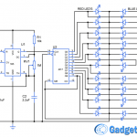
Everyone loves to play with LEDs and in fact it is the most fun component to play with in Electronics. So if you are one among of those here we have a LED decorative lights circuit which illustrates LEDs connected in 5 x 5 matrix form to sequence up to 25 LEDs with just three ICs ( one 555 and two 4017 ) and 10 transistors. This circuit can be expanded up to a 100 LED by using successive stages of the 4017 counters.
CIRCUIT DIAGRAM:
WORKING OF DIY LED DECORATIVE LIGHTS CIRCUIT:
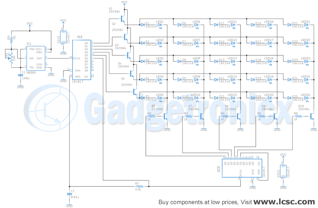
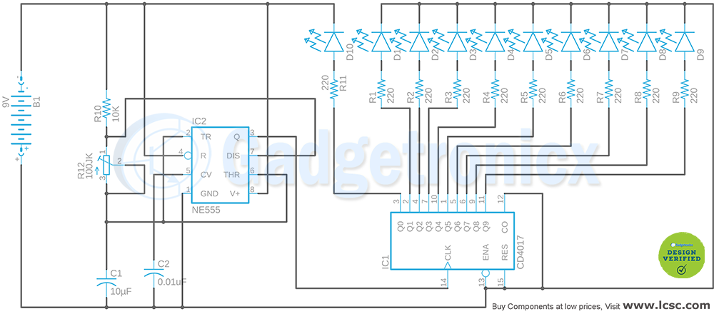
In this circuit LEDs can be in the form of a 5×5 matrix. In this circuit IC 555 provides the clock pulse that drives the entire circuit. IC 555 is wired as an Astable multivibrator which is characterized by generating square wave pulse of fixed frequency.
CD4017:
For those who are not aware IC 4017 is a decade counter which increments the count in output pins with each incoming clock pulse. The two 4017 decade counters control the LEDs in these 5 rows and 5 columns. In this connection type one LED will be selected depending on the output pin in each of those decade counters. For example if Q1 of IC2 is high and Q1 of IC3 IC is high LED1 will be active and lights up.
The output of IC2 increments and activates Q2 when the next clock pulse is fed from IC 555. Since no direct clock pulse is fed to IC3 the Q1 output remain active and this instant LED2 will be activated and lights up. With each progressing clock pulse from IC 555 outputs of IC2 increments and activates output pins Q2,Q3,Q4 and Q5 respectively. This activates LED3, LED4, LED5 respectively.
When output Q6 of IC2 gets activated it feeds the clock pulse to IC3 and resets the IC2 itself. Now the output of IC2 resets back to Q1 and Q2 output of IC3 will be activated. In this instant LED6 will light up. Now with each incoming pulse from IC 555 the output of IC2 increments and as a result activating LED7, LED8, LED9, LED10. Once the Q6 of IC2 goes high it again resets itself and feeds next pulse to IC3. The cycle repeats activating the remaining LEDs one by one from top to bottom of the matrix.
The timing of activation of LEDs depends on the frequency of clock pulse from IC 555. The LEDs can be arranged in any manner you desire making it more interesting lighting effect.
LED STAGE:
The LED lights operate at about 200mA at 3 volts. The supply voltage is set to 5 volts and 4017 IC output will drop about one volt. The transistors act as a switch to activate the LEDs. The voltage on the emitter transistors in rows will be about 0.7 volts less than the base so the LED voltage will be about 3 volts just as much as they needed.
PARTLIST:
- Capacitor 100uF(1), 0.05uF (1)
- Diode 1N4148
- Integrated Circuit NE555
- 25 LED Multi-Color
- Transistor NPN 2N3904 ( 10 )
- Resistor 10k (10), 1k (5), 3.3k
- Integrated Circuit CD4017 ( 2 )
- Potentiometer 10k
Hope this circuit was useful to you to decorate your home. You can use this circuit to use even 100 LEDs with little modification. Do try them and let us know about it in the comment box below. Happy DIY 🙂



Hello All,
Nice diagram of DIY LED DECORATIVE LIGHTS CIRCUIT.
Please can you send version with 100LED’s.
Do you also have printed board?
Besat regards, Miran
I put 3 rows of leds on breadboards, wired it all up, then powered on. Not all leds lit up, even after changing them and checking the circuit, whereas the opposite was true of other leds. Some lit up and repeatedly lit up, the same 2 or 4, with others coming on and going off.