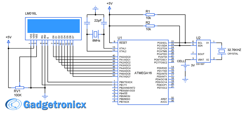
Digital clocks revolutionize the way we live our daily life as it helps people to stick with their schedule. This article will teach you to build your own Digital clock using DS1307 RTC Chip with Atmega16 microcontroller. As we all know that DS1307 is a simple real time clock chip which shows seconds,minute,hours,day,date and year. We have used a simple 16×2 LCD along with it to display all the data obtained from the RTC chip using AVR microcontroller.
DESIGN OF DIGITAL CLOCK USING AVR :
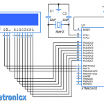
This system was designed using a simple RTC chip ds1307 and AVR microcontroller. The RTC chip keeps track of the seconds,minutes,hours,day,month and year. This chip feeds the AVR with the real time parameters. The fed parameters was then displayed in a simple LCD screen. The RTC was programmed initially with the desired values such as seconds, minutes, hours and so on through I2C interface. After writing into the chip , it starts tracking the time which will be read and displayed in the LCD screen.
RTC DS1307:
This a simple Real time chip aka RTC which is widely used in many systems where real time is necessity. This chip consumes less power and can run with a back up battery supply. This chip supports I2C protocol through which the data transfer occurs. This Chip consists of Readable/Writable registers where it holds the time parameters and keep track of it.
If we want to make this chip run from our desired time, we want to write the registers with the data’s that is time parameters of our desire. Later we can read from those registers to know about the real time values. Read detailed description mode of usage about this chip in this Working of RTC chip DS1307. I suggest you to go through that article before proceeding further.
STEPS TO PROGRAM:
- Initialize the controller to communicate using I2C protocol.
- Send D0 to the RTC chip indicating that the controller is about to write.
- Send address of the register you are about to start writing data, followed by writing time parameter to respective registers.
- Transmit stop condition to terminate the I2C communication.
- Now start the communication and send D1 to the chip indicating the read operation from the chip.
- Set the initial address and start reading the parameters and display the values in the LCD screen, put it in a infinite loop.
CODE:
#include<avr/io.h>
#include<stdio.h>
#define F_CPU 8000000UL
#include<util/delay.h>
#include<avr/interrupt.h>
char value[3];
char days[7][3]={"SUN","MON","TUE","WED","THU","FRI","SAT"};
char position[8]={0x00,0x88,0x85,0x8d,0xc5,0xc8,0xcb};
int i,time;
int j=0;

void i2c_init()           //Initializing i2c Communication
{
  TWSR=0x00;
  TWBR=0x47;
  TWCR=0x04;
}


void i2c_start()          //Starting I2C communication
{
  TWCR=(1<<TWINT)|(1<<TWSTA)|(1<<TWEN);
  while((TWCR &(1<<TWINT))==0);
}

void i2c_stop()            //Stopping I2C communication
{
  TWCR=(1<<TWINT)|(1<<TWSTO)|(1<<TWEN);
}

void i2c_write(char data)       //Writing through I2C
{
  TWDR=data;
  TWCR=(1<<TWINT)|(1<<TWEN);
  while((TWCR &(1<<TWINT))==0);
}

unsigned char i2c_read()        //Read through I2C
{
  TWCR=(1<<TWINT)|(1<<TWEN)|(1<<TWEA);
  while(!(TWCR &(1<<TWINT)));
  return TWDR;
}


void data(char *txt)          //Data writing routine for LCD
{
  PORTB|=(1<<1);
  while(*txt!='\0')
  {
  PORTA=*txt++;
  PORTB|=(1<<0);
  _delay_ms(1);
  PORTB&=~(1<<0);
  _delay_ms(1);
  }
}

void cmd(char comm)         //Command writing routine for LCD
{
   PORTA=comm;
   PORTB&=~(1<<1);
   PORTB|=(1<<0);
   _delay_ms(1);
   PORTB&=~(1<<0);
   _delay_ms(1);
}

void time_set(void)         //Setting time
{
  i2c_init();
  i2c_start();
  i2c_write(0xD0);       //LCD write
  i2c_write(0x00);       //Setting writing address
  i2c_write(0x00);       //Seconds
  i2c_write(0x00);       //Minutes
  i2c_write(0x16);       //Hours
  i2c_write(0x00);       //Days
  i2c_write(0x31);       //Date
  i2c_write(0x05);       //Month
  i2c_write(0x15);       //Year
  i2c_stop();
  _delay_ms(2);
}


void time_write()             //Writing Present time to LCD
{
 if((i==2)|(i==4)|(i==5))     //Setting positions in LCD
   {
    cmd(position[i]);
    data(value);
    data("-");
   }
  else if(i==3)
  {
    cmd(position[i]);
    data(&days[time][0]);
  }

  else if(i==7){}

  else
   {
    cmd(position[i]);
    data(value);
   }
}


int main(void)
{
 DDRB=0x03;
 DDRA=0xff;
 DDRC=0x00;
 cmd(0x38);
 cmd(0x0c);
 cmd(0x01);
 cmd(0x80);
 data("TIME:");
 cmd(0xc0);
 data("DATE:");
 time_set();
 j=0;
 while(1)
   {
   i2c_start();
   i2c_write(0xD0);
   i2c_write(0x01);        //Writing starting address to read from minutes
   i2c_stop();
   _delay_ms(2);
   i2c_start();
   i2c_write(0xD1);
   for(i=1;i<=7;i++)
      {
      time=i2c_read();
      sprintf(&value[0],"%x",time&0xF0);   //int to char conversion
      sprintf(&value[1],"%x",time&0x0F);
      time_write();
      }
   i2c_stop();
   _delay_ms(2);
   }
 return 0;
}

how can i print sec in lcd ..what is changes in program
Nd yeah i want to know about how to time and date change mean that how to access lcd printed date and time by using button or any kind of component which can change time and date??and how to interface it
Shaunak,
Interface buttons to the controller using external interrupt write routine to change the time parameters based on the each key press. Hope this helps!
Yes i get the time and date get on lcd but one problem with that it seen like bellow
Time:00:63
Date:31-3-99
In program
Time:16:00
Date:31-05-2015
So what is the problem for this error occur??
Shunak,
Seems like a odd problem! Check the code once again , you getting any errors or warnings in the code? You getting the day displayed in the LCD?
How can i get todays date in this??
Shaunak,
Initially you need to set the date and time to the chip and after that it will track and take care of the days, years and time.
How can I set the date & time to the chip?
Dinuka,
Well if you look at the address mapping of the DS1307 04H is for setting the date and 00 , 01 and 02 is for setting the time respectively. All you have to do is write appropriate input to these registers
How would I go about setting an alarm using the DS1307?
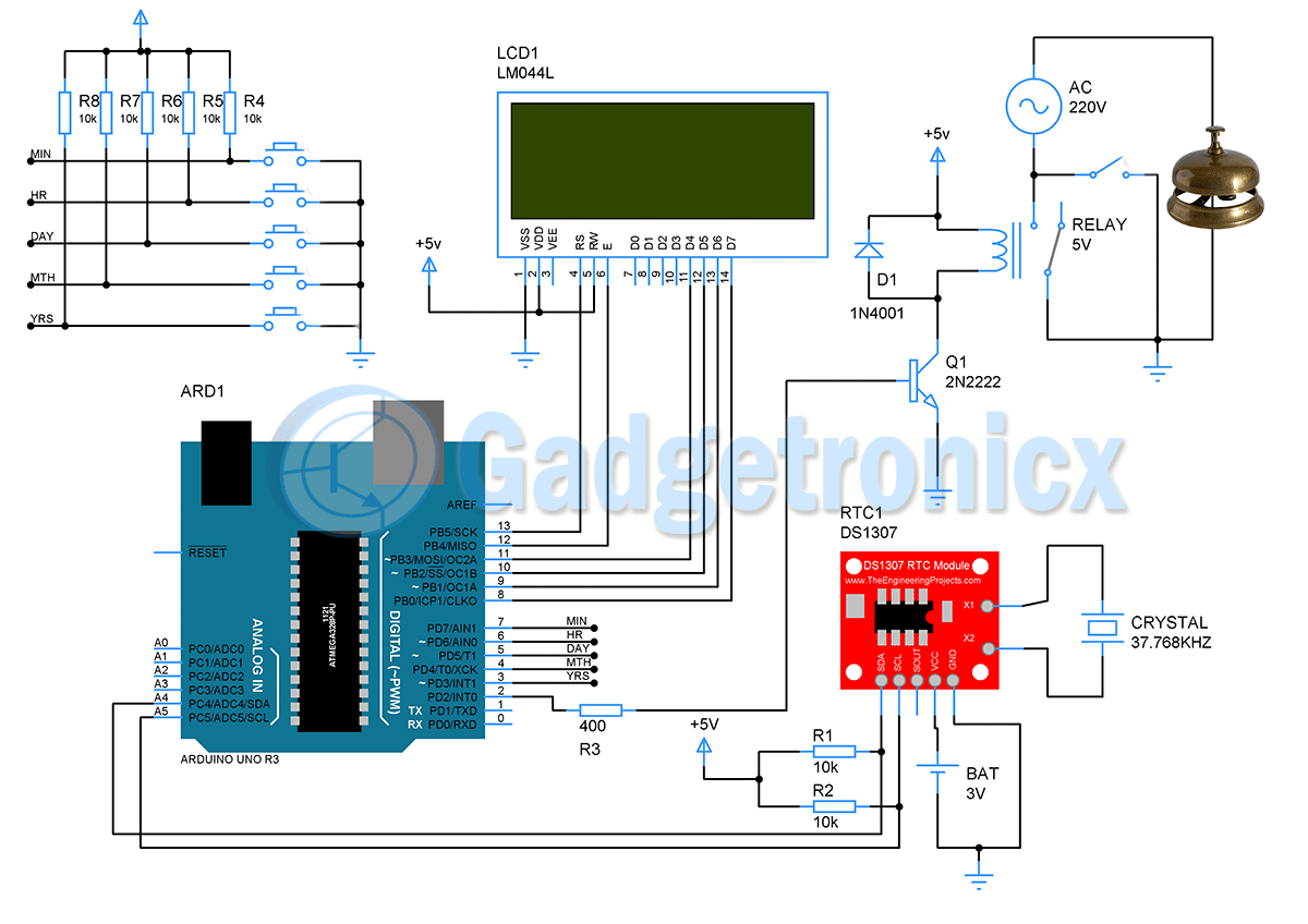
Simple, Obtain the data from DS1307 and then compare it with the alarm data you need to set. If matches set the ring by adding buzzer and so.
I have tried to compile this code in arduino and it gives me errors.
PortA was not declared in this scope. Line 61
Jared,
Well am not aware of Arduino compiler, this code was built using AVR studio.
What is the variable name that the minutes are stored in? I would like to add a condition to output an led at a certain miinute
The time is is read from from RTC module and stored in the time variable in the above code