Clap activated light circuits are something which is used to activate or turn on by means of a simple clap. You might have seen some of this before but building one could be really fun. This clap activated switch circuit can be used for any means of activation not just to turn on the lights. Let’s look into the working of this cool circuit.
WORKING OF CLAP ACTIVATED LIGHT CIRCUIT:
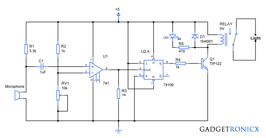
The working of this circuit starts with Microphone which is used to sense the clap. The output of the Microphone was fed into a non inverting pin 3 of a simple operational amplifier. While a voltage divider network using R2 and RV1 provides the reference voltage for the non inverting pin 2 of the op amp.
Clap generally occurs in a short burst of time with high pitch, hence it results in a peak voltage across the pin 3 of the op amp over a short interval of time. So adjust the reference voltage of the non inverting pin accordingly so that the circuit activates only when senses a clap and not to other speech signals.
Now when no clap is sensed there will no voltage across the pin 2 hence output of the op amp remains in low state. A pull down resistor R3 was used to make sure that the pin 6 stays low in the absence of any input signal. When a clap is sensed the output of the Op amp goes high and feeds a positive high output to the flip flop connected to it.
A simple JK flip IC 74109 was used as an activator here where it was wired to toggle it’s output state with every edge of the high input. So whenever a clap is sensed the output of the op amp triggers the flip flop and activates the relay by means of a transistor switch. This state will remain until another clap is sensed and the flip flop will toggle its output state (i.e turn off the relay/light) as soon it encounters another clap.
A simple LED with a current limiting resistor was added for indication and a 5V relay was used as an activator here for the light. You can replace the light with the thing you desire to activate it on a clap. And your clap activated light is ready
NOTE:
- The clap activation must be done with the trial and error method by adjusting the VR1 until the light gets activated with just clap.
- Make sure your switching transistor Q1 current rating is good enough to handle the relay.
- You can use any Op-amp and JK flip flop IC here.



At first,if we create clap on clap off,what things we need?
The circuit diagram shows the required components. Kindly check them out
How have you wired the relay in?
CAN YOU HELP ME LIST ALL THE COMPONENTS USED BY USING ISIS?
how to tailor it to use the above circuit to activate on my voice?
Your voice? That’s too much to ask from this simple circuit. You can alter it to make this circuit to switch whenever a voice occurs but it will not work just for your voice alone. Any noise similar to voice will trigger the circuit. Just adjust the RV1.