Cell Phones have became an essential gadget in our day to day life. But it will be annoying when used at inappropriate places like hospitals, schools, theatres and so. For this purpose Cellphone Jammer circuit is used to block the signals received by the cell phones ceasing them to work properly. But in some countries using Jammers are prohibited and will be penalized if you do, so make sure you are legally allowed to build and use this circuit.
WORKING OF CELL PHONE JAMMER CIRCUIT:
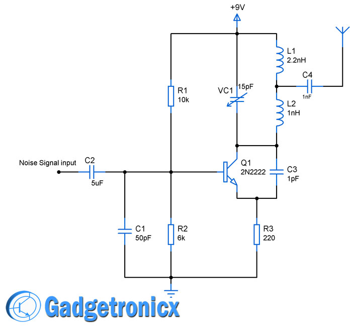
Generally Cell phones operate at a particular frequency which depends on the network and technology they are using. But usually most of the mobile phones operate at a band between 800Mhz to 950 Mhz. The above circuit uses similar operating frequency range which will cancel out signals from the Base stations to cell phones. This in turn will confuse the cell phones and cease them from working.
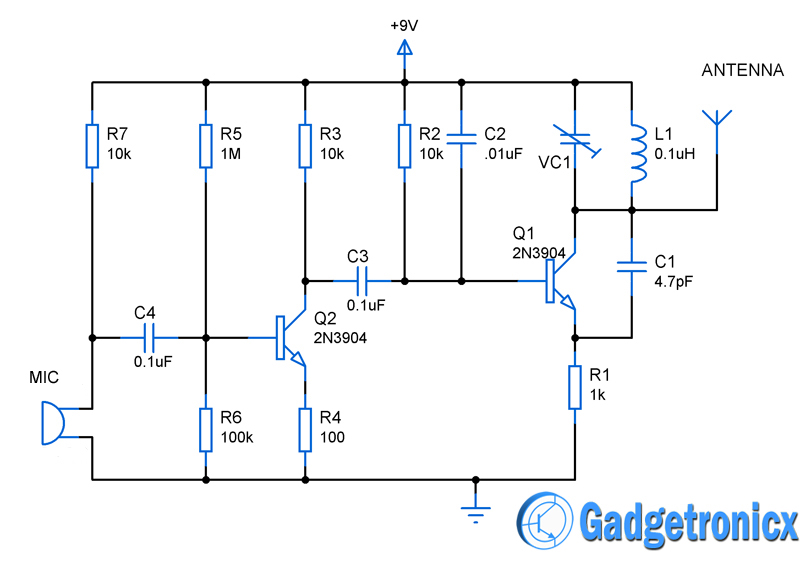
The working of this circuit starts with feeding a random noise signal signal as input. The signal can be of anything (square, sine or speech signals ) which is fed to capacitor C2 to remove the DC components in it. The signal is then fed in to a RF oscillator built around high frequency NPN transistor Q1 2N2222. Resistors R1 and R2 are used to fix the biasing voltage to the base of the transistor.
The tank Circuit used in the above circuit is built using two inductors and a Variable cap which is used to adjust the output frequency obtained from this circuit. This circuit is capable of giving frequency output ranging from 725Mhz to 2.8GHz. Altering the position of the trimmer will vary the output frequency. The frequency output can be determined by the equation.
F = 1/ 2¶ √LC
Based on this equation we need to fix cap value as 11pf to obtain the frequency range of about 850Mhz approximately. You can use this equation to fix the LC values required for you desired output frequency.
Capacitor C3 was used to produce sustaining output frequency oscillations. And Capacitor C4 was used to remove the DC components from the final output RF signal. You can use an RF antenna along with this circuit or use old mobiles antenna along with this circuit for signal transmission. This circuit have a range of about 20 feet radius and capable of killing cell phones within that.
NOTE:
- Use this circuit with caution since some countries banned usage of cell phone jammers and you can be penalized as well.
- Use the above given equation to fix the LC values for your desired frequency.
- You may need to operate your jammer in frequency based on the operating frequency used by the cell phones in your kill zone.

2N2222 can’t oscillate at this frequence instead we use BFR90
How to give a noise signal input sir,pls anyone reply me
The 2N2222 specified will probably not oscillate normally, because its gain at these frequencies would be incredibly low. There are transistors that’ll work, but not for cheap. The 2N5179 will function just fine, as it is intended as an RF oscillator up to 2GHz. It’s also through-hole, for ease of construction. It’s also $5.51 for just one of them through Digi-Key at the time of this post. It will also need different biasing, because its gain is different: R1 needs to be 1.18k and R2 needs to be 715 ohms. These are E96 values. For E24 use 1.1k and 680. C1 should be raised to 430pF, to compensate for the lower resistance it’s bypassing. Otherwise, it should work the same. The 2N5179 has a 4th pin, connected to its case. This can be left floating or connected to ground. It acts as a shield against noise, but that’s obviously not a concern here LOL
Good Day Lupin Wolfe, what transistor can be replacement for 2N5179 from Multisim software? SO THAT THE OUTPUT SIGNAL CAN HAVE ENOUGH POWER.
where to connect the battery + and –
The schematic is clearly labeled – +9 volts (near top) and ground symbol (negative side of battery) at the bottom. Do you know how to read a schematic?
what should be the frequency of input signal>>??????? plzz answer
Any frequency in the audio range would work (20Hz to 20Khz) but I would suggest a ‘sweep’ generator to vary the noise over this range. The waveshape doesn’t matter – sine, square or triangle waves will do the job.
what sources of noise would you use?
Phillip,
It could be any random signal that could intervene the cellphone’s working signal frequency
This will not work for jamming cellphone because The working frequencyof transistor 2n2222 is only 3000Mhz so how it can jam that cell that works on 0.800 to 2GHz Frequency
the Philips 2N2222 data sheet say FT=300 Mhz, so its very hard to reach the 800 Mhz lower Cellphone frecuencies???
This violates FCC regulations and you can end up with a fine / jail time….
does it really work?
Yes it should in theory. However in practical you need more patience to get the frequency right and block the signal.
What is the rf power output?
That is the radiofrecuency wich will allow blocking your service provider signal
Less than 1 watt.
the output current of the circuit is to low to get enough power, is there a way to increase it ?