 |
| Motor Controller Circuit using L293D |
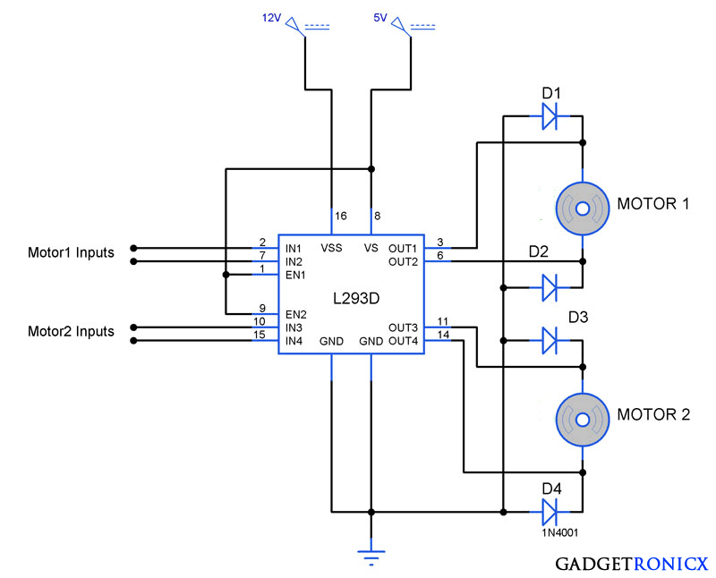
Motor Controller driver IC’s are widely used in electronic circuits to control the motor with ease and to drive it efficiently. L293D is a similar motor driver mostly employed along with the Mircocontrollers to perform the motor action. This IC is capable of driving two motors at a single time in either direction and it can even provide drive currents up to 1A at voltages 4.5V to 36V. The above circuit illustrates the bidirectional motor controller using this simple L293D. Lets move into the working of this circuit.
WORKING OF L293D:
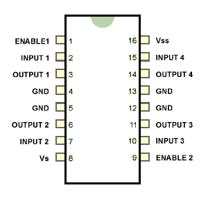 |
| Pin Diagram of L293D |
The L293D is a 16 pin IC which is known for their efficiency in controlling DC motors. There are two types of supply voltage for this IC Vs and Vss. Vs is meant for its own internal operation and it will not use this input for driving motors. This Vs input voltage should not exceed 7 V or it will damage the IC. Vss is meant for supplying power to the motor we are about to drive, for example if we are going to drive a 12V motor you should give 12V input to this 16th pin Vss.
Enable pins are meant to make the respective motor drivers ready to operate, supplying high signal will activate the corresponding drivers. Enable1 for motor 1 and Enable 2 is for motor 2. Input pins 2, 7, 10, 15 are used to operate the motor in your desired direction. Output pins 3 & 6 should be connected to motor 1 , Pins 11 & 14 should be connected to motor 2. Here is a logic table for the inputs of L293D and the motor state corresponding to that input.
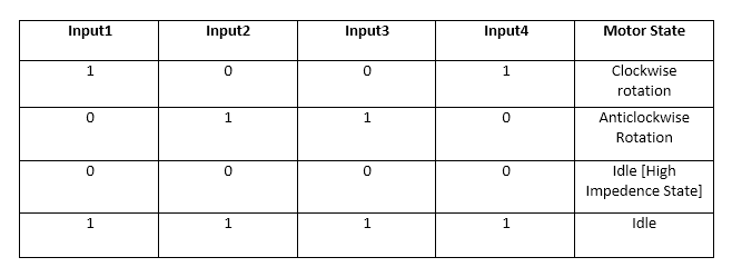 |
| Input Logic table of L293D |
WORKING OF CIRCUIT:
The working this Bidirectional motor controller is pretty straightforward and easy to understand. Since both the motors are used, the EN1 & EN2 are connected to high state. Since we are using a 12v motor here Vss was supplied with 12v DC supply. Motors was connected along with diodes along each output pins for offering protection to the IC’s from reverse current.
Motor inputs IN1, IN2, IN3, IN4 are the pins we need to provide logic to drive the motor in desired direction. High in the IN1 pin and low in IN2 pin will make the Motor1 to rotate in Clockwise Direction. Refer above logic table for various logic inputs to the pins and corresponding motor states. This circuit is capable of driving motors up to 1A provided with optimum power supply.



Pingback: Temperature controlled fan using PIC 16F877A • Tech Projects
Can I replace the diode 1N4001 for 1n4004 or 1N4007?
Felipe,
Yes you can.
Hey,
Just wanted to say thanks- your simple and easy to follow guide tought me how to use the l293dne in no time. =)
So yeah, just thanks for an awesome tutorial!