 |
| 8051 Microcontroller |
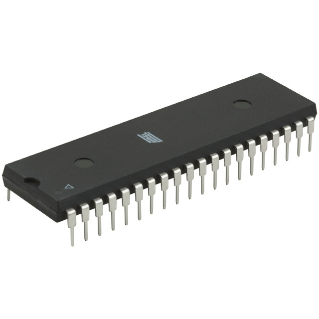
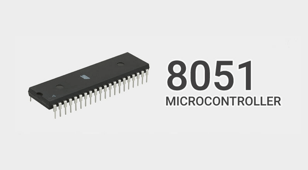
8051 Microcontroller series is a basic controller which is ideal for every embedded engineer to start with. Even though there are many modern microcontrollers the 8051 still holds its significance due to its capability to develop complex systems using it. This tutorial focuses on covering the basics of 8051 microcontroller and will give you clear idea about how to use ports, how to load values into it and how to make controller work as per your requirements.
This article will only cover the basics concepts needed to program the 8051 Microcontroller. It is advised to refer a book for detailed explanation of 8051 Microcontroller.
BASICS OF 8051 MICROCONTROLLER:
 |
| Bits and Bytes |
Bits are the fundamental part of information or data based on which the Microcontroller operates. The bit can take value either as 1 or 0.
Bytes are defined as the collection of 8 bits. Generally in 8051 Microcontroller the data’s are fed as input or obtain output by means of byte values.
REGISTERS:
 |
| register |
Registers are small memory element in a Microcontroller where a specific value can be loaded to perform a specific task. It can vary in size such as 8-bit or 16-bit registers. The LSB marks the initial or Least significant bit and MSB marks the last or Most significant bit.
HEX VALUES IN MICROCONTROLLER:
 |
| Hex values |
In Microcontrollers we use hex values to represent the data fed into it because of its simplicity in representation and easier understanding. For example if we have a 8bit data such as 0000 1111 it is easier to represent it as 0F (Refer the above table).
In 8051 Microcontrollers we will use hex values to load values into any register or port. And it is represented as 0x0F. Whereas the “0x” stands for using data in the hex format. Here is an online converter to convert values from binary to Hex which you can use to determine equivalent hex values for your binary inputs
ACCESSING 8051 PORTS:
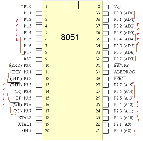
Ports is the term used to define the collection of output pins in a microcontroller. In 8051 each port has 8 pins associated to it. There are two ways of using these ports in 8051 Microcontroller and you can use any method which fits you while considering the flexibility of code.
SBIT – Single bit which was used to activate or deactivate a specific pin or bit in the port of a 8051 microcontroller. Say for example if you need to access Pin 5 of the Port 0 in your 8051 Controller you must give it as
sbit i=P0^5
where i is the variable name assigned by the user which can be altered for your readability.
SFR- Special function registers are the registers which are accessed by means of its address. The address of the ports in the 8051 controller is given below.
PORT 0 – 0x80
PORT 1 – 0x90
PORT2 – 0xA0
PORT3 – 0xB0
To access Port 1 using SFR we should give it as
sfr i=0x90
Where i is the name assigned by the user which can be altered for your readability. Whereas the Ports of the Microcontroller can also be accessed by means of the Port numbers. For example you need to access Port 2, you can mention it as “P2”
Lets see a Sample code to give you a clear idea about the basic 8051 Programming.
CODE:
#include<regx51.h>
sbit led=P1^0;      //Selecting first bit of the port 1 in 8051
sfr leds=0xA0;       //Accessing the whole Port 2 using address
void delay();
void main()
{
leds=0xFF;         //Activating all the pins of Port 2 high
led=1;                //Making just pin 0 of Port 1 high
delay();              //A software delay
leds=0x00;        //Deactivate all the pins of Port 2 low
led=0;               //Deactivating pin 0 of Port 1 low
}
void delay()
{
unsigned int i;
for(i=0;i<=5000;i++);        //A delay by using for loop
}

There is a mistake in the description of the code:
leds=0x0F; //Making Lower four bits ‘1’ & higher four as ‘1’ of port 2
it should be:
leds=0x0F; //Making Lower four bits ‘1’ & higher four as ‘0’ of port 2
Hi,
Thanks for pointing it out corrected now