Plant watering system evolved through various stages where primitive irrigation systems possess many drawbacks as it fails to conserve water and human energy. So introducing Automation in it can help us to overcome these drawbacks and pave way to conserve water. This can be done with a simple Soil moisture sensor and a Microcontroller, AVR in our case. You can try out this system to automate watering the plants in your home at affordable cost.
SOIL MOISTURE SENSOR:
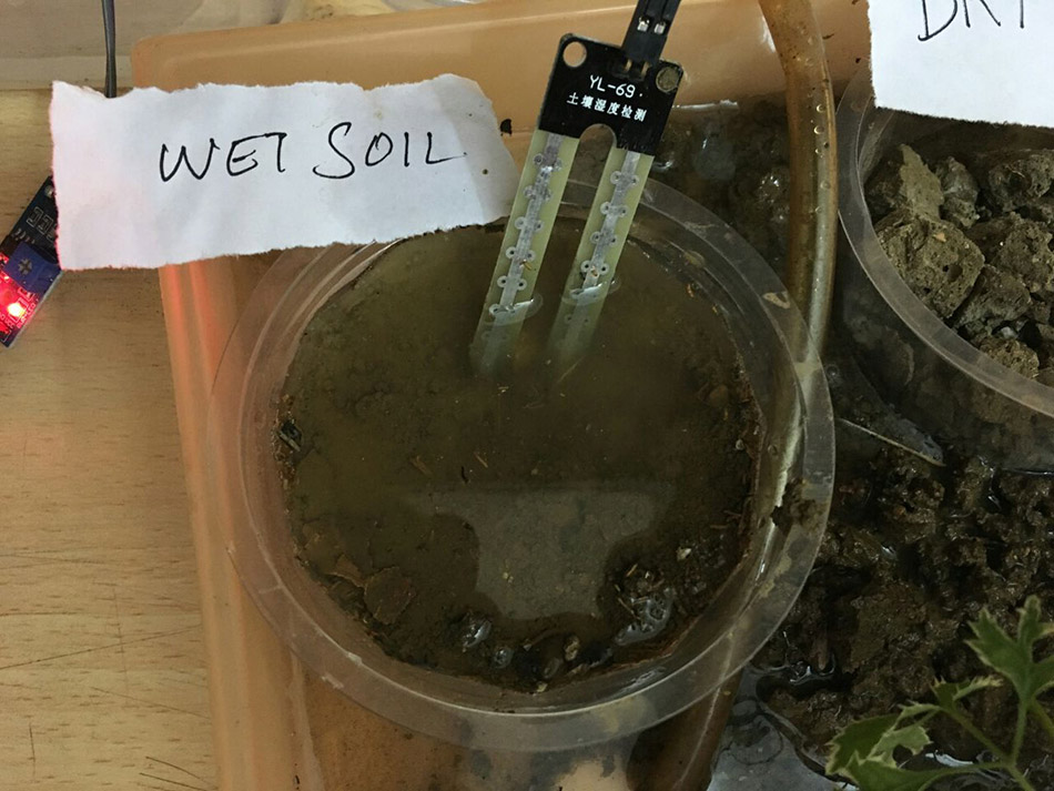
The Soil moisture sensor plays a crucial factor in this plant watering system. There are several ways to measure the moisture of the soil. We are going to measure the moisture level by the conductivity property of the moist soil. We all know that the moist soil conducts electricity better than the dry one. And the impedence level of the dry soil is higher than the moist one.
 |
| Source : www.instructables.com |
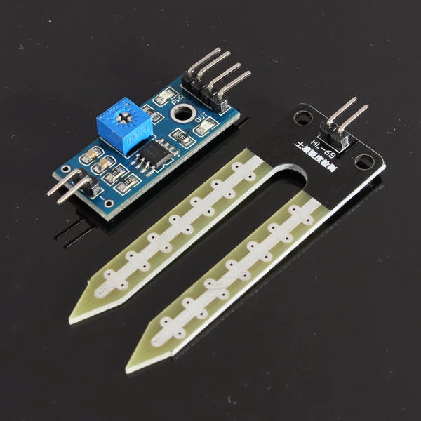
Here we are going to employ a Simple soil moisture sensor KDQ11 which you can which you can buy from ebay. This sensor is associated with comparator LM-393 so whenever the soil is moist the sensor gives low signal as output and high in the case of dry soil. The analog output from this sensor module is fed to the A/D pin of the controller for conversion.
ALTERNATE METHOD TO MEASURE SOIL MOISTURE:
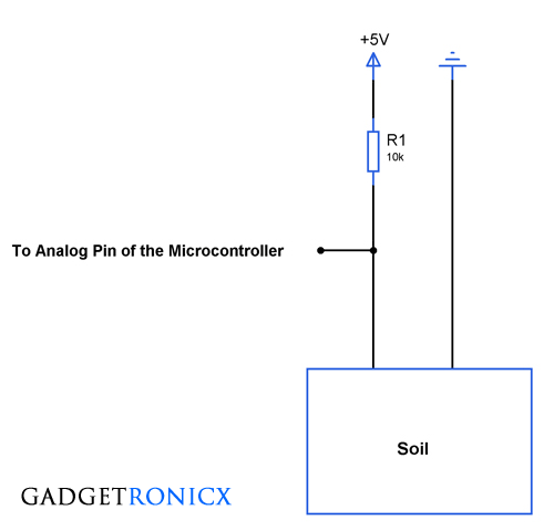
For those you cannot get Soil moisture sensor, you can make one by your own, it may be unorthodox but will be effective. Insert two wires to the dry soil and measure the resistance of it. And again repeat the same by pouring some water to the soil (moist condition). Now you have to built a voltage resistor network using a resistor and the soil. Here the soil acts as a potentiometer which varies its resistance based on its condition.
Calculate the resistor value you are about to use based on the resistance you have done before in wet and dry condition. And determine the trigger point in which you system have to switch the pump on.
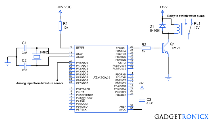
And last but not the least Pump actuator, use a relay which is capable of switching heavy load such as pumps. The power transistor TIP122 is used to switch the Relay On/Off based on the moisture content of the soil.
CODE:
This code was built using AVR studio 4.
#include<avr/io.h>
int adc(void);
void pump(void);
int adc_value;
int main(void)
 {
  DDRC=0x01;                          //Defining PC0 as output
  ADCSRA=0x87;                    //Setting the mode of operation
  ADMUX=0x00;                     //Selection of channel and bit alignment
  while(1)
   {
     adc_value=adc();                //reading moisture level
     pump();                               //Pump activator routine
   }
   return 0;
 }

int adc(void)
 {
   int lower_bits,higher_bits,result;
   ADCSRA|=(1<<6);              //Turning on conversion
   while(ADIF==0);
   lower_bits=ADCL;
   higher_bits=ADCH;
   result=lower_bits|higher_bits<<8;         //Accessing converted value by shifting
   return result;
 }

void pump(void)
 {
  if(adc_value>=600)                                //Pump ON trigger point
   {
     PORTC|=(1<<0);
   }
  else if(adc_value<=700)                        //Pump Off trigger point
   {
     PORTC&=~(1<<0);
   }
 }
NOTE:
- The Trigger point of pump activation depends on the soil so make your calibration before setting the On and off point. Here i have used 600 as triggering point for pump On (low moisture) and 700 for turning off the pump(high moisture).
- Set the triggering points in such a way to keep some difference in between them to avoid relay chattering.

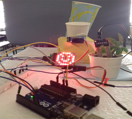
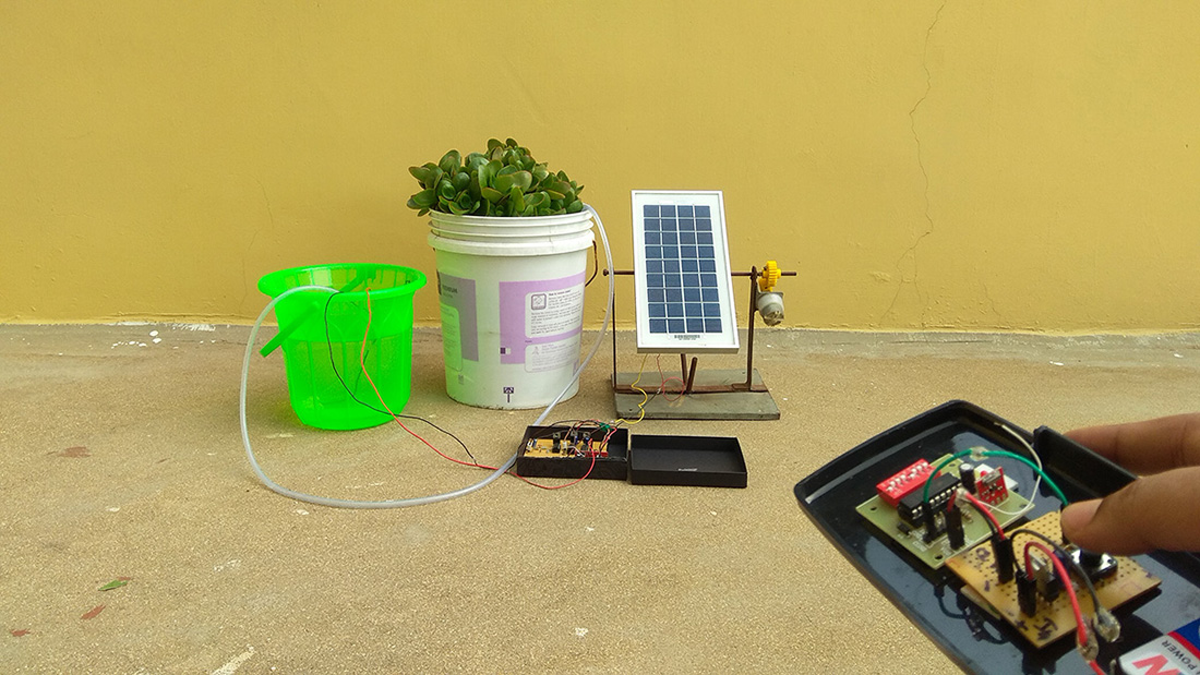
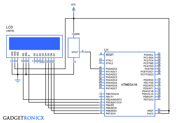
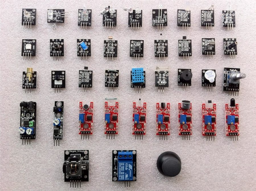
I want to make this project at home, the only microcontroller i got here is a arduino Uno rev 3. Will the code work with this controller?
Kind regards,
Arno,
Well the above code was built using AVR studio. I don’t think you can use it directly on Arduino IDE you need to modify it. Although try this project link -> https://www.gadgetronicx.com/auto-plant-watering-happiness-monitoring/
Frank, thanks for the answer
I made a bootloader for arduino in atmel studio so i can use my arduino in AVR studio.
So my question actually was if i could use thise code on my arduino since its a atmega 328p chipset?
And if not what should i adjust to make it work?
Thanks already!
Arno,
Got your question. Few modifications are required, Atmega16 and Atmega328 are different so you need to modify the code so that it matches with ATmega328 MCU. For example you need to modify the lines 7,8,9 and other lines similar to that. These lines of code control the ADC functionality and output pin of ATmega16 so you want to check the datasheet of Atmega328 and modify code accordingly. Hope it helps
How can I connect the LCD to the microcontroller and also its code.
Sanjeev,
Here is the tutorial for LCD interface -> https://www.gadgetronicx.com/programming-lcd-4-8-bit-mode-8051/
Thank you.
Sir,could you please upload the code for atmega to operate motor on and off with moisture sensor? (automatic irrigation system)
Sneha,
The above code is for Atmega16
this code is giving an error during simulation
Hallo Guys
I’m a power engineering student so I don’t really understand this code but I want to build a machine which almost works like automatic irrigation system.
Help me out guys. I want to build a machine which automatically control and maintain the humidity between 40% to 50%. if humidity rises above 50% relay N1 must switch ON and if humidity drops below 40%, relay N2 must switch ON.
How can I modify the code to fit this problem? thank you for helping me
Hi Jonas,
You need to first determine the voltage output that your Moisture sensor will exhibit at the point you consider the moisture level is 50% and 40%. Say for example you are measuring 2.5v from the moisture sensor a small calculation needs to be done. We are using 10bit adc so our max bit resolution is 2^10= 1024. So the reference voltage divided the maximum number of bits will be 5v / 1023 ( 0 to 1023) which will give a value of 4.88mv. This is minimum voltage value for which a MCU will increase the value in its register example value 1 if input is 4.88mv value 2 if input is 9.76mv and so. So we have 2.5v at the input so our register value will be “520”. Considering 2.5v is the Voltage exhibited at 40% of moisture you need to substitute this value in the line 31 of the code replacing 600.
Okay, thank you very much Frank
Jonas, No problem
dear sir,
your projects are very interesting.
sir i kindly requesting to you sir, please tell me c code of monitoring of 8051 mic interface with DHT12 SENSOR and operate with the relay1 and relay2,at 31degre temprature and 56% humidity respectivily
ATTACH TO ME THIS PROJECT THAT IS SIMULATION WITH PROGRAM CODE
sir the code of autoirrigation using atmega16 which you had provided is compiled successfully but its not working on proteus. so what settings on proteus are needed?
Saurabh,
It may not work in simulation, kindly try it real time
sir can you please give me your email id i have some queries regarding this project.it will be so kind of you.thank you
Awais,
Please post your queries in this comment section so that other readers will also get benefited.
Hello, instead of relay, i used l293d motor driver. So I changed the code little bit…
#include
int adc(void);
void pump(void);
int adc_value;
int main(void)
{
DDRC=0x03;
ADCSRA=0x87;
ADMUX=0x00;
while(1)
{
adc_value=adc();
pump();
}
return 0;
}
int adc(void)
{
int lower_bits,higher_bits,result;
ADCSRA|=(1<<6);
while(ADIF==0);
lower_bits=ADCL;
higher_bits=ADCH;
result=lower_bits|higher_bits<=600)
{
PORTC = 0b00000001;
}
else if(adc_value<=550)
{
PORTC = 0b00000011;
}
}
I declared pin 0 & 1 of port c as o/p and changed the last 4 line. Actually my sensor o/p is 4.2v (at dry) and 2.1(at wet). But in both cases(i.e. wet & dry) the port C pin 0 & 1 coming high. There should be pin 0 high & pin 1 low in dry condition.
I tried so many times, but I failed. Can you please help me?
Already I am very grateful to you for your kind help.
Thank you.
Subhankar,
You missed the if condition before the line
{
PORTC = 0b00000001;
}
Also what exactly you intend to do in this line “result=lower_bits|higher_bits<=600)"?