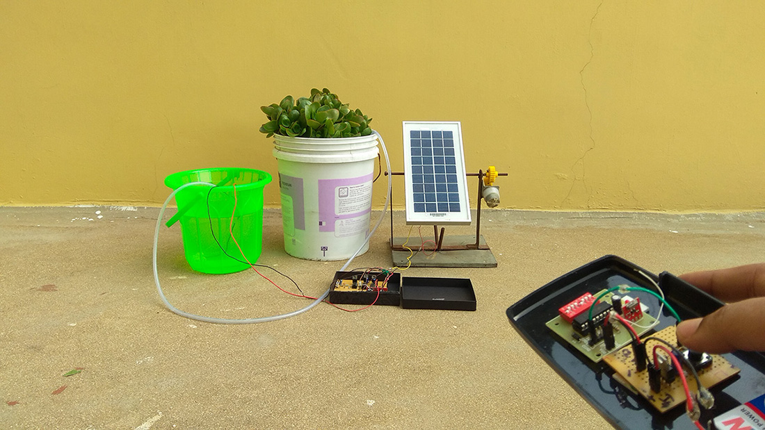
Plant watering system evolved through various stages where primitive irrigation systems possess many drawbacks as it fails to conserve water and human energy. So introducing Automation in it can help us to overcome these drawbacks and pave way to conserve water. This can be done with a simple Soil moisture sensor and a Microcontroller, AVR in our case. You can try out this system to automate watering the plants in your home at affordable cost.
SOIL MOISTURE SENSOR:
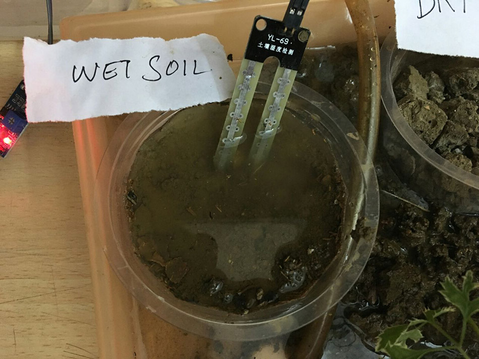
The Soil moisture sensor plays a crucial factor in this plant watering system. There are several ways to measure the moisture of the soil. We are going to measure the moisture level by the conductivity property of the moist soil. We all know that the moist soil conducts electricity better than the dry one. And the impedence level of the dry soil is higher than the moist one.
 |
| Source : www.instructables.com |
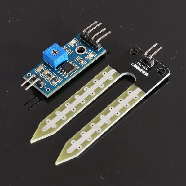
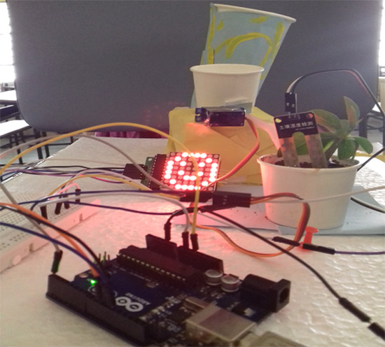
Here we are going to employ a Simple soil moisture sensor KDQ11 which you can which you can buy from ebay. This sensor is associated with comparator LM-393 so whenever the soil is moist the sensor gives low signal as output and high in the case of dry soil. The analog output from this sensor module is fed to the A/D pin of the controller for conversion.
ALTERNATE METHOD TO MEASURE SOIL MOISTURE:
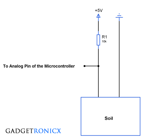
For those you cannot get Soil moisture sensor, you can make one by your own, it may be unorthodox but will be effective. Insert two wires to the dry soil and measure the resistance of it. And again repeat the same by pouring some water to the soil (moist condition). Now you have to built a voltage resistor network using a resistor and the soil. Here the soil acts as a potentiometer which varies its resistance based on its condition.
Calculate the resistor value you are about to use based on the resistance you have done before in wet and dry condition. And determine the trigger point in which you system have to switch the pump on.
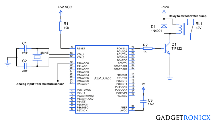
And last but not the least Pump actuator, use a relay which is capable of switching heavy load such as pumps. The power transistor TIP122 is used to switch the Relay On/Off based on the moisture content of the soil.
CODE:
This code was built using AVR studio 4.
#include<avr/io.h>
int adc(void);
void pump(void);
int adc_value;
int main(void)
 {
  DDRC=0x01;                          //Defining PC0 as output
  ADCSRA=0x87;                    //Setting the mode of operation
  ADMUX=0x00;                     //Selection of channel and bit alignment
  while(1)
   {
     adc_value=adc();                //reading moisture level
     pump();                               //Pump activator routine
   }
   return 0;
 }

int adc(void)
 {
   int lower_bits,higher_bits,result;
   ADCSRA|=(1<<6);              //Turning on conversion
   while(ADIF==0);
   lower_bits=ADCL;
   higher_bits=ADCH;
   result=lower_bits|higher_bits<<8;         //Accessing converted value by shifting
   return result;
 }

void pump(void)
 {
  if(adc_value>=600)                                //Pump ON trigger point
   {
     PORTC|=(1<<0);
   }
  else if(adc_value<=700)                        //Pump Off trigger point
   {
     PORTC&=~(1<<0);
   }
 }
NOTE:
- The Trigger point of pump activation depends on the soil so make your calibration before setting the On and off point. Here i have used 600 as triggering point for pump On (low moisture) and 700 for turning off the pump(high moisture).
- Set the triggering points in such a way to keep some difference in between them to avoid relay chattering.

Hello sir, I have some trouble with the code. Actually I haven’t understand the code of line No. 8 & 9 (i.e. ADCSRA=0x87; ADMUX=0x00;)
and from 21 to 25
(i.e. ADCSRA|=(1<<6);
while(ADIF==0);
lower_bits=ADCL;
higher_bits=ADCH;
result=lower_bits|higher_bits<<8;).
If you explain, it would be helpfull for me.
Thank you.
Subhankar,
Line 8 and 9 – ADCSRA and ADMUX are registers in AVR controller and am feeding a 8 bit value to it. The value was in hex format so 0x87 and 0x00.
Line 21 to 25 – They are bit wise operations in C, have a read on this topic you will understand
Hello, can i use L293d motor driver instead of relay?
Subhankar,
What do you want to achieve, please elaborate it might help me understanding it better
By sensing the soil moisture, I just want to control the motor pump. When soil is dry motor pump will start and when wet it will stop.
For that can I use motor driver instead of relay?
Subhankar,
That shouldn’t be a problem at all, connect the output pin of MCU directly to the input pin of L293D removing the R2 and Q1 from the circuit. The L293D takes logic input from the MCU and power input should be given to the chip based on the Voltage rating of the motor you are gonna use.
Thank You…
Frank Donald,
Is there anything wrong in the code? because after burning it, i am getting low voltage for wet soil and high voltage for dry soil from the analog sensor input… but the problem is, i am always getting high voltage at PC0 in borh cases.. there in no change in the values for dry and wait soil.. in such case where is the actual problem.. is there anything wrong in the circuit design or in the code? I have followed everyting you have described here. please help. And one more thing, can you please tell me the proper way of measuring the output value I am getting from PC0 which in turn is swutching on/off the pump?
SS,
I guess the problem lies within the sensor you are using here. May i know what type of sensor you are using in your project is it a ready made module or a voltage divider one?
How I will know moisture sensor values? Will It be displayed? Is there any way to know/display the input coming from the moisture sensor so that I can know the exact value of the moisture? please help.
Hasan,
Frank Donald,
You can use your multimeter for this job. Measure the output voltage from the sensor using in both dry and humid conditions. Calibrate this voltage and convert them to get the ADC value which in turn will give you the range ex.600 & 700 to add in your code.
Frank Donald,
“Calibrate this voltage and convert them into ADC value”- Will you please give a more details of this line? How will I do this? I am a newbie. Please reply
Thanks.
Hasan,
The sensor which i have mentioned KDQ11 gives low voltage output when soil is moist and vice versa. So let’s consider you are measuring o/p voltage of sensor in dry conditions say it gives around 4.5V (high). To calibrate you must see the step size of our controller which is 5V/1024 where 5 is reference voltage for adc and 1024 is 2^10 where ADC is 10 bits in size.
So 5V/1024 = 4.88mv for each step. So dividing our measured voltage 4.5 by step size , 4.5/4.88mv = 922, we get the range for Pump on trigger point( Refer Code). Similarly if the moist conditions give out voltage like 2.5 repeat the same division which results in 2.5/4.88mv = 512, which is Pump Off trigger point (Refer Code). This is all about calibration.
If you are still unclear go through basics of ADC working and calibration in microcontrollers. It will help you to get cleared. Hope it helps.
Hi,
I am a newbie. Can you please tell me how many softwares in total will be needed to complete the project? And can you please tell me the steps of building the project (for example: After building the above circuit along with moisture sensor, what will be the next step to test if the code is working or not? ). Please help.
James,
You only need AVR studio software to build your code no other softwares required. After building circuit you first need to measure your moisture sensor values in real time because the range of values which i have given in the code (600 & 700) may vary based on the type of soil and other environmental factors. So first measure the soil humidity without pouring water and then repeat the same by pouring some water in it. This gives you two moisture values which you can use in your code. Hope it helps, let me know your project outcome.
How will I see the moisture values as an output from the sensor? Is is possible to display it? Will I need any additional component to display it?
James,
You can use your multimeter for this job. Measure the output voltage from the sensor using Multimeter in both dry and humid conditions. Calibrate this voltage and convert them into ADC value. This will give you the two range of ADC values to add in your code.
can you please explain the role of R2,D1 and Q1?
AA,
The Role of R2 is to limit the base current flowing to the transistor. D1 is to prevent the reverse current flow and damage the whole circuit. Q1 acts as a switch to the turn the relay on since the MCU pin cannot source current to the relay directly.
Why we are using the capacitors C1,C2 and the crystal oscillator (8 MHZ) and forming a circuit? What is the role of this?
SK,
I guess you need to brush up some basics. For every MCU to work it needs to fed with clock pulse of predefined frequency without it the MCU cannot operate. Whereas the Caps C1 and C2 are attached to the crystal for sustained oscillations from the crystal.
Ok but, at the right hand side, apart from the relay, what is the use of the other components like C3,R2 and also Q1?
sorry. it will work. but i dont get why there is void in arguments. it is used to write there () when function is no void…
Hello,
Well i guess you are confused about it. The term void means empty that is we are not gonna pass any argument into the function however leaving empty makes them unspecified. This stackoverflow discussion gives you a great idea “Is there a difference between foo(void) and foo() in C++ or C” . kindly leave comment with your name or profile next time. Cheers
function acc() is VOID. it means no return information. so adc_value cannot be loaded by result of adc(). because adc() is vodi….
adc_value=adc(); < — This cannot work, because you the prototype of the adc() function is VOID !!!
Can’t get your point, “adc()” function was declared as “int” it will work correctly.