 |
| Pocket Size alarm using IC 741 |
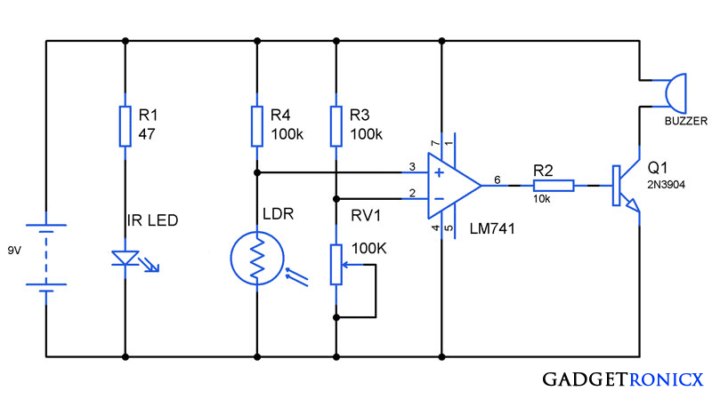
Alarms are of great use in real world. It alerts people when there is a breach also building one will be easy task. You might have come across different types of alarm circuits varying with their complexity and simplicity. Here is a circuit which has a highlighting feature of miniature size so that it can be carried around easily. This anti theft alarm circuit is very simple will not be suitable for complex theft prevention but it will form a great hobby circuit. This circuit comprises of two parts a transmitter and receiver where infra red beam is used in between to detect intrusion by thieves.
WORKING OF ANTI THEFT ALARM CIRCUIT:
The working of the above circuit begins with the transmitter part. An Infra Red LED is powered with a simple battery. A Resistor was used to limit the current flow through the LED and it must be chose depending on the current and voltage consumption of the LED. A high range IR LED must be chosen to employ in this circuit to improve the range obtained.
The receiver forms the next part of the circuit. A LDR was used to detect the infra red beam from the transmitter. As we all know that LDR shows low resistance when light intensity fall on it. It will be high and high resistance when there is no incident light. This circuit uses the above principle to detect any break in the IR beam.
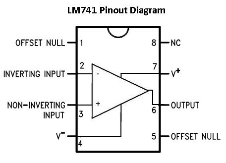 |
| IC 741 Pin Diagram |
The next stage was formed by Op Amp IC 741 which is employed as a comparator here. Voltage to the inverting and non inverting terminals of the 741 was fed through two potential dividers LDR & R4 and RV1 & R3. When IR beam is incident on LDR it gives low resistance and voltage in the point where R4 and LDR is tied together will be low. Therefore the output of Op Amp will keep the buzzer OFF.
When the IR beam is cut off by any intruder, LDR will provide high resistance resistance and the voltage at R4 and LDR point will be high. This makes the op amp to give high signal output and in turn switches the buzzer using a transistor switch.
SETTING UP THIS CIRCUIT:
You need to adjust the POT RV1 when aligning the Transmitter to the receiver. RV1 should be adjusted in such a way to push the Op Amp to produce low signal output when IR signal is incident on LDR. This also can be used to adjust the sensitivity of the beam detection used in the circuit.
MODIFICATIONS:
The above circuit can also be modified to guard a particular object placed in between the transmitter and receiver. In this IR beam interrupted by the object to be guarded. In case any intruder picks the object the obstruction will be removed and this trigger the buzzer to sound the alarm. For this you need to exchange the pin connection potential dividers and PNP transistor must be used as switch.



An LDR DECREASES with light, the explanation is wrong in the post, when light falls on it, the resistance is low, and hence 2 resistors in series, the one with the lower resistance will have a lower voltage and the transistor will saturate negative, keeping the BJT, off! When the light is interrupted, the LDR RESISTANCE increase, the P.D. ACROSS the LDR increases and the BJT saturates positive, being NPN, IT turns on, and the siren goes on.
sorry made the changes now 🙂
To provide the greatest range, select a matched IR LED and IR phototransistor. Also, choose the narrowest beam angle to limit the spread of the IR beam. This will concentrate the IR for the greatest detection range. Similarly, the IR phototransistor lens will concentrate the incident IR light to provide the maximum sensitivity while preventing stray reflected IR light from other sources from contaminating the source and reducing the sensitivity. The main problem with this circuit and any similar circuits is the continuous power draw of the IR emitter and detector circuits. Without an electrical power supply souorce, the circuit will quickly use up the batterieis and render the detector inoperative. Ron H.
I completely agree with all the things you mentioned above. The above circuit will not provide much efficiency and i have mentioned it above. This circuit will come handy in case of short range and usage. However this can initiate readers to think different to make a better one and also understand the practical working of comparators